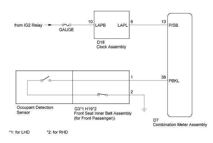
SEAT BELT WARNING SYSTEM > Front Passenger Side Seat Belt Warning Light Malfunction |
| 1.READ VALUE USING GTS (P-SEATBELT BUCKLE SW) |
Connect the GTS to the DLC3.
Turn the ignition switch to ON.
Turn the GTS on.
Enter the following menus: Body Electrical / Combination Meter / Data List.
Read the Data List according to the display on the GTS.
| Tester Display | Measurement Item/Range | Normal Condition | Diagnostic Note |
| P-Seatbelt Buckle SW | Front passenger seat belt buckle switch signal/ON or OFF | ON: Front passenger seat belt fastened OFF: Front passenger seat belt not fastened | - |
|
| ||||
| OK | |
 |
| 2.PERFORM ACTIVE TEST USING GTS (AIRBAG SYSTEM) |
Connect the GTS to the DLC3.
Turn the ignition switch to ON.
Turn the GTS on.
Enter the following menus: Body Electrical / Combination Meter / Active Test.
Perform the Active Test according to the display on the GTS.
| Tester Display | Test Part | Control Range | Diagnostic Note |
| Front Passenger Side Seat Belt | Front passenger side seat belt warning light | ON/OFF | - |
|
| ||||
| OK | ||
 | ||
| ||
| 3.INSPECT CLOCK ASSEMBLY |
Remove the clock assembly (Click here).
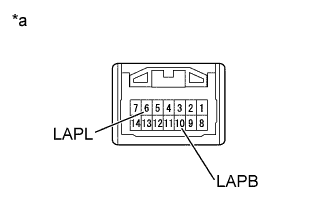 |
Apply battery voltage to the connector and check the illumination condition.
| Condition | Specified Condition |
| Battery positive (+) → 10 (LAPB) Battery negative (-) → 6 (LAPL) | Front passenger side seat belt warning light comes on |
| *a | Component without harness connected (Clock assembly) |
|
| ||||
| OK | |
|
| 4.CHECK HARNESS AND CONNECTOR (BATTERY - CLOCK ASSEMBLY - COMBINATION METER ASSEMBLY) |
Disconnect the D18 clock assembly connector.
Disconnect the D7 combination meter assembly connector.
Measure the resistance according to the value(s) in the table below.
| Tester Connection | Condition | Specified Condition |
| D18-6 (LAPL) - D7-13 (P/SB) | Always | Below 1 Ω |
| D18-6 (LAPL) - Body ground | Always | 10 kΩ or higher |
Measure the voltage according to the value(s) in the table below.
| Tester Connection | Condition | Specified Condition |
| D18-10 (LAPB) - Body ground | Ignition switch ON | 11 to 14 V |
|
| ||||
| OK | ||
| ||
| ||
| 5.INSPECT SEPARATE TYPE FRONT SEAT CUSHION PAD (OCCUPANT DETECTION SENSOR) |
Inspect the separate type front seat cushion pad (occupant detection sensor) (Click here).
|
| ||||
| OK | |
|
| 6.INSPECT FRONT SEAT INNER BELT ASSEMBLY (FOR FRONT PASSENGER) |
Inspect the front seat inner belt assembly (for front passenger) (Click here).
|
| ||||
| OK | |
|
| 7.CHECK HARNESS AND CONNECTOR (FRONT SEAT INNER BELT ASSEMBLY - COMBINATION METER ASSEMBLY - BODY GROUND) |
Disconnect the G3 front seat inner belt assembly connector. (for LHD)
Disconnect the H19 front seat inner belt assembly connector. (for RHD)
Disconnect the D7 combination meter assembly connector.
Measure the resistance according to the value(s) in the table below.
| Tester Connection | Condition | Specified Condition |
| G3-1 - D7-38 (PBKL) | Always | Below 1 Ω |
| G3-1 - Body ground | Always | 10 kΩ or higher |
| G3-2 - Body ground | Always | Below 1 Ω |
| Tester Connection | Condition | Specified Condition |
| H19-1 - D7-38 (PBKL) | Always | Below 1 Ω |
| H19-1 - Body ground | Always | 10 kΩ or higher |
| H19-2 - Body ground | Always | Below 1 Ω |
|
| ||||
| OK | ||
| ||
| ||

