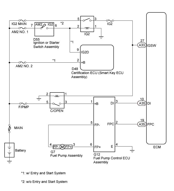
SFI SYSTEM > Fuel Pump Control Circuit |
| 1.PERFORM ACTIVE TEST USING GTS (CONTROL THE FUEL PUMP/SPEED) |
Connect the GTS to the DLC3.
Turn the ignition switch to ON.
Turn the GTS on.
Enter the following menus: Powertrain / Engine / Active Test / Control the Fuel Pump/Speed.
Check whether the fuel pump operating sound occurs when performing the Active Test on the GTS.
| Result | Proceed to |
| Fuel pump operating sound does not occur | A |
| Fuel pump operating sound occurs | B |
|
| ||||
| A | |
 |
| 2.PERFORM ACTIVE TEST USING GTS (CONTROL THE FUEL PUMP) |
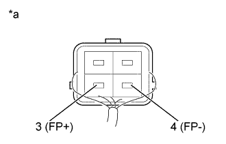 |
Connect the GTS to the DLC3.
Turn the ignition switch to ON.
Turn the GTS on.
Enter the following menus: Powertrain / Engine / Active Test /Control the Fuel Pump Duty.
Measure the voltage according to the value(s) in the table below.
| Tester Connection | Condition | Specified Condition |
| 3 (FP+) - 4 (FP-) | FPC Duty: 25% | 3.2 to 4.05 V |
| 3 (FP+) - 4 (FP-) | FPC Duty: 80% | 8.8 to 12.5 V |
| *a | Component without harness connected (Fuel Pump) |
Enter the following menus: Powertrain / Engine / Active Test / Control the Fuel Pump/Speed.
Measure the voltage according to the value(s) in the table below.
| Tester Connection | Condition | Specified Condition |
| 3 (FP+) - 4 (FP-) | ON (FPC Duty: 25%) | 9.0 to 14.0 V |
|
| ||||
| OK | |
|
| 3.CHECK HARNESS AND CONNECTOR (ECM - FUEL PUMP CONTROL ECU ASSEMBLY) |
Disconnect the ECM connector.
Disconnect the fuel pump control ECU assembly connector.
Measure the resistance according to the value(s) in the table below.
| Tester Connection | Condition | Specified Condition |
| A35-19 (FPC) - G12-2 (FPC) | Always | Below 1 Ω |
| Tester Connection | Condition | Specified Condition |
| A35-19 (FPC) or G12-2 (FPC) - Body ground | Always | 10 kΩ or higher |
|
| ||||
| OK | |
|
| 4.REPLACE FUEL PUMP ASSEMBLY |
Replace the fuel pump assembly (Click here).
| NEXT | |
|
| 5.CHECK CONFIRM WHETHER MALFUNCTION HAS BEEN SUCCESSFULLY REPAIRED |
Check the fuel pump operation .
|
| ||||
| OK | ||
 | ||
| ||
| 6.REPLACE FUEL PUMP CONTROL ECU ASSEMBLY |
Replace the fuel pump control ECU assembly (Click here).
| NEXT | |
|
| 7.CHECK CONFIRM WHETHER MALFUNCTION HAS BEEN SUCCESSFULLY REPAIRED |
Check the fuel pump operation .
|
| ||||
| OK | ||
| ||
| ||
| 8.INSPECT FUEL PUMP CONTROL ECU ASSEMBLY (POWER SOURCE VOLTAGE) |
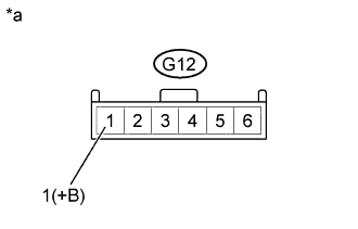 |
Disconnect the fuel pump control ECU assembly connector.
Turn the ignition switch to ON.
Measure the voltage according to the value(s) in the table below.
| Tester Connection | Condition | Specified Condition |
| G12-1 (+B) - Body ground | Ignition switch ON | 11 to 14 V |
| *a | Front view of wire harness connector: (to fuel pump control ECU) |
|
| ||||
| OK | |
|
| 9.CHECK HARNESS AND CONNECTOR (FUEL PUMP - FUEL PUMP CONTROL ECU ASSEMBLY) |
Disconnect the fuel pump connector.
Disconnect the fuel pump control ECU assembly connector.
Measure the resistance according to the value(s) in the table below.
| Tester Connection | Condition | Specified Condition |
| G7-4 (FP-) - G12-5 (FP-) | Always | Below 1 Ω |
| G7-3 (FP+) - G12-6 (FP+) | Always | Below 1 Ω |
| Tester Connection | Condition | Specified Condition |
| G7-4 (FP-) or G12-5 (FP-) - Body ground | Always | 10 kΩ or higher |
| G7-3 (FP+) or G12-6 (FP+) - Body ground | Always | 10 kΩ or higher |
|
| ||||
| OK | |
|
| 10.INSPECT FUEL PUMP ASSEMBLY |
Inspect fuel pump assembly (Click here).
|
| ||||
| OK | |
|
| 11.CHECK HARNESS AND CONNECTOR (FUEL PUMP CONTROL ECU ASSEMBLY - ECM) |
Disconnect the ECM connector.
Disconnect the fuel pump control ECU assembly connector.
Measure the resistance according to the value(s) in the table below.
| Tester Connection | Condition | Specified Condition |
| A35-19 (FPC) - G12-2 (FPC) | Always | Below 1 Ω |
| G12-4 (E)- Body ground | Always | Below 1 Ω |
| Tester Connection | Condition | Specified Condition |
| A35-19 (FPC) or G12-2 (FPC) - Body ground | Always | 10 kΩ or higher |
|
| ||||
| OK | |
|
| 12.REPLACE FUEL PUMP CONTROL ECU ASSEMBLY |
Replace the fuel pump control ECU assembly (Click here).
| NEXT | |
|
| 13.CHECK CONFIRM WHETHER MALFUNCTION HAS BEEN SUCCESSFULLY REPAIRED |
Check the fuel pump operation .
|
| ||||
| OK | ||
| ||
| ||
| 14.CHECK HARNESS AND CONNECTOR (C/OPEN RELAY - FUEL PUMP CONTROL ECU ASSEMBLY) |
Remove the C/OPEN relay from the engine room relay block assembly.
Disconnect the fuel pump control ECU assembly connector.
Measure the resistance according to the value(s) in the table below.
| Tester Connection | Condition | Specified Condition |
| C/OPEN relay terminal 3 - G12-1 (+B) | Always | Below 1 Ω |
| C/OPEN relay terminal 1 - Body ground | Always | Below 1 Ω |
| Tester Connection | Condition | Specified Condition |
| C/OPEN relay terminal 3 or G12-1 (+B) - Body ground | Always | 10 kΩ or higher |
|
| ||||
| OK | |
|
| 15.INSPECT TERMINAL VOLTAGE (C/OPEN RELAY) |
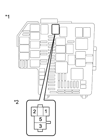 |
Remove the C/OPEN relay from the engine room relay block assembly.
Measure the voltage according to the value(s) in the table below.
| Tester Connection | Condition | Specified Condition |
| C/OPEN relay terminal 5 - Body ground | IG ON | 11 to 14 V |
| *1 | Engine Room Relay Block Assembly |
| *2 | C/OPEN Relay Terminal |
|
| ||||
| OK | |
|
| 16.CHECK HARNESS AND CONNECTOR (C/OPEN RELAY - ECM - IG2 RELAY) |
Disconnect the ECM connector.
Remove the C/OPEN relay and IG2 relay from the engine room relay block assembly.
Measure the resistance according to the value(s) in the table below.
| Tester Connection | Condition | Specified Condition |
| C/OPEN relay terminal 2 - A33-27 (IGSW) | Always | Below 1 Ω |
| C/OPEN relay terminal 2 - IG2 relay terminal 3 | Always | Below 1 Ω |
| Tester Connection | Condition | Specified Condition |
| C/OPEN relay terminal 2, A33-27 (IGSW) or IG2 relay terminal 3 - Body ground | Always | 10 kΩ or higher |
|
| ||||
| OK | ||
| ||
| ||

