 |
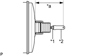
Set the push rod length as shown in the illustration.
| *1 | Lock Nut |
| *2 | Brake Master Cylinder Push Rod Clevis |
| *a | Push Rod Length |
- Push rod length:
- 155.2 mm (6.11 in.)
BRAKE BOOSTER (for LHD) > INSTALLATION |
| 1. INSTALL BRAKE MASTER CYLINDER PUSH ROD CLEVIS |
Temporarily install the lock nut and brake master cylinder push rod clevis to the brake booster assembly.
|
Set the push rod length as shown in the illustration.
| *1 | Lock Nut |
| *2 | Brake Master Cylinder Push Rod Clevis |
| *a | Push Rod Length |
Tighten the lock nut.
| 2. INSTALL BRAKE BOOSTER ASSEMBLY |
Install the 4 nuts to the brake booster assembly.
| 3. INSTALL FRONT NO. 2 BRAKE TUBE |
Connect 2 clips and install the front No. 2 brake tube.
Using a union nut wrench 12 mm, connect the front No. 2 brake tube from the brake actuator.
| 4. INSTALL FRONT NO. 1 BRAKE TUBE |
Connect 2 clips and install the front No. 1 brake tube.
Using a union nut wrench 12 mm, connect the front No. 1 brake tube from the brake actuator.
| 5. CONNECT VACUUM TUBE CONNECTOR HOSE |
Install the vacuum tube connector hose.
| 6. INSTALL PUSH ROD PIN |
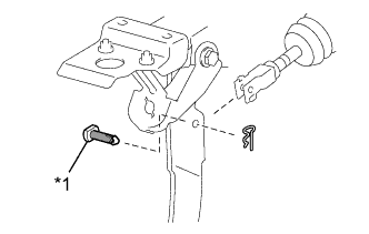 |
Apply lithium soap base glycol grease to the push rod pin.
| *1 | Push Rod Pin |
 | Lithium Soap Base Glycol Grease |
Connect the brake master cylinder push rod clevis to the brake pedal support assembly with the push rod pin, and install a new clip as shown in the illustration.
| 7. INSTALL BRAKE MASTER CYLINDER SUB-ASSEMBLY |
| 8. CHECK AND ADJUST BRAKE PEDAL (for Automatic Transmission) |
| 9. CHECK AND ADJUST BRAKE PEDAL (for Manual Transmission) |
| 10. INSTALL TCM (for Automatic Transmission) |
| 11. INSTALL LOWER NO. 1 INSTRUMENT FANEL AIRBAG ASSEMBLY (w/ Knee Airbag) |
| 12. INSTALL NO. 1 INSTRUMENT PANEL UNDER COVER SUB-ASSEMBLY (w/o Knee Airbag) |
Connect each connector.
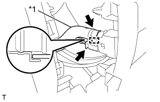 |
for Automatic Air Conditioning System for RHD:
Connect the connector.
Engage the guide and connect the aspirator hose.
| *1 | Aspirator Hose |
Engage the 4 claws.
Engage the 4 clips to install the No. 1 instrument panel under cover sub-assembly.
Install the 2 screws.
| 13. INSTALL INSTRUMENT SIDE PANEL LH (w/o Knee Airbag) |