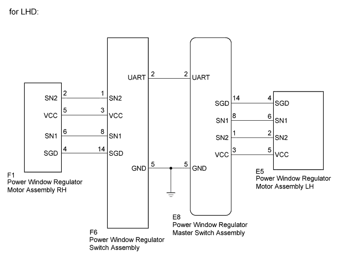
DTC B2311 Driver Side Motor Malfunction |
DTC B2314 Passenger Side Motor Malfunction |
| DTC No. | DTC Detection Condition | Trouble Area |
| B2311 |
|
|
| B2314 |
|
|
| 1.CHECK DTC OUTPUT |
Clear the DTC (Click here).
Check for DTCs (Click here).
| Result | Proceed to |
| DTC B2311 is output | A |
| DTC B2314 is output | B |
|
| ||||
| A | |
 |
| 2.READ VALUE USING GTS |
Connect the GTS to the DLC3.
Turn the ignition switch to ON.
Turn the GTS on.
Enter the following menus: Body Electrical / Master Switch / Data List.
According to the display on the GTS read the Data List.
| Tester Display | Measurement Item/Range | Normal Condition | Diagnostic Note |
| Current D Sensor Fail Mode1 | Driver side sensor fail mode1(power of sensor malfunction) /Detected or Not Detected | Not Detected | - |
| Current D Sensor Fail Mode2 | Driver side sensor fail mode2(Pulse sensor1 malfunction) /Detected or Not Detected | Not Detected | - |
| Current D Sensor Fail Mode3 | Driver side sensor fail mode3(Pulse sensor2 malfunction) /Detected or Not Detected | Not Detected | - |
| Current D Sensor Fail Mode4 | Driver side sensor fail mode4(Pulse direction error) /Detected or Not Detected | Not Detected | - |
| Current D Sensor Fail Mode5 | Driver side sensor fail mode5(Pulse stop) /Detected or Not Detected | Not Detected | - |
| Current D Sensor Fail Mode6 | Driver side sensor fail mode6(Dead zone opening direction error) /Detected or Not Detected | Not Detected | - |
| Result | Proceed to |
| NG | A |
| OK | B |
|
| ||||
| A | |
|
| 3.CHECK HARNESS AND CONNECTOR (POWER WINDOW REGULATOR MASTER SWITCH - POWER WINDOW REGULATOR MOTOR) |
Disconnect the E8*1 or F6*2 power window regulator master switch assembly connector.
Disconnect the E5*1 or F1*2 power window regulator motor assembly connector.
Measure the resistance according to the value(s) in the table below.
| Tester connection | Condition | Specified condition |
| E8-3 (VCC) - E5-5 (VCC)*1 | Always | Below 1 Ω |
| E8-14 (SGD) - E5-4 (SGD)*1 | Always | Below 1 Ω |
| F6-3 (VCC) - F1-5 (VCC)*2 | Always | Below 1 Ω |
| F6-14 (SGD) - F1-4 (SGD)*2 | Always | Below 1 Ω |
| Tester connection | Condition | Specified condition |
| E8-8 (SN1) - E5-6 (SN1)*1 | Always | Below 1 Ω |
| F6-8 (SN1) - F1-6 (SN1)*2 | Always | Below 1 Ω |
| Tester connection | Condition | Specified condition |
| E8-1 (SN2) - E5-2 (SN2)*1 | Always | Below 1 Ω |
| F6-1 (SN2) - F1-2 (SN2)*2 | Always | Below 1 Ω |
| Tester connection | Condition | Specified condition |
| E8-1 (SN2) - E5-2 (SN2)*1 | Always | Below 1 Ω |
| E8-8 (SN1) - E5-6 (SN1)*1 | Always | Below 1 Ω |
| F6-1 (SN2) - F1-2 (SN2)*2 | Always | Below 1 Ω |
| F6-8 (SN1) - F1-6 (SN1)*2 | Always | Below 1 Ω |
| Tester connection | Condition | Specified condition |
| E8-1 (SN2) - E5-2 (SN2)*1 | Always | Below 1 Ω |
| E8-3 (VCC) - E5-5 (VCC)*1 | Always | Below 1 Ω |
| E8-8 (SN1) - E5-6 (SN1)*1 | Always | Below 1 Ω |
| E8-14 (SGD) - E5-4 (SGD)*1 | Always | Below 1 Ω |
| F6-1 (SN2) - F1-2 (SN2)*2 | Always | Below 1 Ω |
| F6-3 (VCC) - F1-5 (VCC)*2 | Always | Below 1 Ω |
| F6-8 (SN1) - F1-6 (SN1)*2 | Always | Below 1 Ω |
| F6-14 (SGD) - F1-4 (SGD)*2 | Always | Below 1 Ω |
| Tester connection | Condition | Specified condition |
| E8-1 (SN2) - E5-2 (SN2)*1 | Always | Below 1 Ω |
| E8-3 (VCC) - E5-5 (VCC)*1 | Always | Below 1 Ω |
| E8-8 (SN1) - E5-6 (SN1)*1 | Always | Below 1 Ω |
| E8-14 (SGD) - E5-4 (SGD)*1 | Always | Below 1 Ω |
| F6-1 (SN2) - F1-2 (SN2)*2 | Always | Below 1 Ω |
| F6-3 (VCC) - F1-5 (VCC)*2 | Always | Below 1 Ω |
| F6-8 (SN1) - F1-6 (SN1)*2 | Always | Below 1 Ω |
| F6-14 (SGD) - F1-4 (SGD)*2 | Always | Below 1 Ω |
| Tester connection | Condition | Specified condition |
| E8-3 (VCC)*1 Body ground | Always | 10 kΩ or higher |
| E8-14 (SGD)*1 Body ground | Always | 10 kΩ or higher |
| F6-3 (VCC)*2 Body ground | Always | 10 kΩ or higher |
| F6-14 (SGD)*2 Body ground | Always | 10 kΩ or higher |
| Tester connection | Condition | Specified condition |
| E8-8 (SN1)*1 -Body ground | Always | 10 kΩ or higher |
| F6-8 (SN1)*2 -Body ground | Always | 10 kΩ or higher |
| Tester connection | Condition | Specified condition |
| E8-1 (SN2)*1 - Body ground | Always | 10 kΩ or higher |
| F6-1 (SN2)*2 - Body ground | Always | 10 kΩ or higher |
| Tester connection | Condition | Specified condition |
| E8-1 (SN2)*1- Body ground | Always | 10 kΩ or higher |
| E8-8 (SN1)*1 - Body ground | Always | 10 kΩ or higher |
| F6-1 (SN2)*2- Body ground | Always | 10 kΩ or higher |
| F6-8 (SN1)*2 - Body ground | Always | 10 kΩ or higher |
| Tester connection | Condition | Specified condition |
| E8-1 (SN2)*1- Body ground | Always | 10 kΩ or higher |
| E8-3 (VCC)*1 - Body ground | Always | 10 kΩ or higher |
| E8-8 (SN1)*1 - Body ground | Always | 10 kΩ or higher |
| E8-14 (SGD)*1 - Body ground | Always | 10 kΩ or higher |
| F6-1 (SN2)*2- Body ground | Always | 10 kΩ or higher |
| F6-3 (VCC)*2 - Body ground | Always | 10 kΩ or higher |
| F6-8 (SN1)*2 - Body ground | Always | 10 kΩ or higher |
| F6-14 (SGD)*2 - Body ground | Always | 10 kΩ or higher |
| Tester connection | Condition | Specified condition |
| E8-3 (VCC)*1 - Body ground | Always | 10 kΩ or higher |
| E8-8 (SN1)*1 - Body ground | Always | 10 kΩ or higher |
| E8-14 (SGD)*1 - Body ground | Always | 10 kΩ or higher |
| E8-14 (SGD)*1 - Body ground | Always | 10 kΩ or higher |
| F6-3 (VCC)*2 - Body ground | Always | 10 kΩ or higher |
| F6-8 (SN1)*2 - Body ground | Always | 10 kΩ or higher |
| F6-14 (SGD)*2 - Body ground | Always | 10 kΩ or higher |
| F6-14 (SGD)*2 - Body ground | Always | 10 kΩ or higher |
|
| ||||
| OK | |
|
| 4.INSPECT POWER WINDOW REGULATOR MOTOR ASSEMBLY |
Remove the power window regulator motor assembly (Click here ).
Inspect the power window regulator motor assembly (Click here).
|
| ||||
| OK | |
|
| 5.REPLACE POWER WINDOW REGULATOR MASTER SWITCH ASSEMBLY |
Temporarily replace the power window regulator master switch assembly with a new or normally functioning one (Click here).
Check the power window regulator master switch assembly operates (Click here).
| Result | Proceed to |
| Does not operate | A |
| Operate | B |
|
| ||||
| A | ||
 | ||
| ||
| 6.READ VALUE USING GTS |
Connect the GTS to the DLC3.
Turn the ignition switch to ON.
Turn the GTS on.
Enter the following menus: Body Electrical / Master Switch / Data List.
According to the display on the GTS read the Data List.
| Tester Display | Measurement Item/Range | Normal Condition | Diagnostic Note |
| Current P Sensor Fail Mode1 | Front passenger side sensor fail mode1(power of sensor malfunction) /Detected or Not Detected | Not Detected | - |
| Current P Sensor Fail Mode2 | Front passenger side sensor fail mode2(Pulse sensor1 malfunction) /Detected or Not Detected | Not Detected | - |
| Current P Sensor Fail Mode3 | Front passenger side sensor fail mode3(Pulse sensor2 malfunction) /Detected or Not Detected | Not Detected | - |
| Current P Sensor Fail Mode4 | Front passenger side sensor fail mode4(Pulse direction error) /Detected or Not Detected | Not Detected | - |
| Current P Sensor Fail Mode5 | Front passenger side sensor fail mode5(Pulse stop) /Detected or Not Detected | Not Detected | - |
| Current P Sensor Fail Mode6 | Front passenger side sensor fail mode6(Dead zone opening direction error) /Detected or Not Detected | Not Detected | - |
| Result | Proceed to |
| NG | A |
| OK | B |
|
| ||||
| A | |
|
| 7.CHECK HARNESS AND CONNECTOR (POWER WINDOW REGULATOR SWITCH - POWER WINDOW REGULATOR MOTOR) |
Disconnect the F6*1 or E8*2 power window regulator master switch assembly connector.
Disconnect the F1*1 or E5*2 power window regulator motor assembly connector.
Measure the resistance according to the value(s) in the table below.
| Tester connection | Condition | Specified condition |
| F6-3 (VCC) - F1-5 (VCC)*1 | Always | Below 1 Ω |
| F6-14 (SGD) - F1-4 (SGD)*1 | Always | Below 1 Ω |
| E8-3 (VCC) - E5-5 (VCC)*2 | Always | Below 1 Ω |
| E8-14 (SGD) - E5-4 (SGD)*2 | Always | Below 1 Ω |
| Tester connection | Condition | Specified condition |
| F6-8 (SN1) - F1-6 (SN1)*1 | Always | Below 1 Ω |
| E8-8 (SN1) - E5-6 (SN1)*2 | Always | Below 1 Ω |
| Tester connection | Condition | Specified condition |
| F6-1 (SN2) - F1-2 (SN2)*1 | Always | Below 1 Ω |
| E8-1 (SN2) - E5-2 (SN2)*2 | Always | Below 1 Ω |
| Tester connection | Condition | Specified condition |
| F6-1 (SN2) - F1-2 (SN2)*1 | Always | Below 1 Ω |
| F6-8 (SN1) - F1-6 (SN1)*1 | Always | Below 1 Ω |
| E8-1 (SN2) - E5-2 (SN2)*2 | Always | Below 1 Ω |
| E8-8 (SN1) - E5-6 (SN1)*2 | Always | Below 1 Ω |
| Tester connection | Condition | Specified condition |
| F6-1 (SN2) - F1-2 (SN2)*1 | Always | Below 1 Ω |
| F6-3 (VCC) - F1-5 (VCC)*1 | Always | Below 1 Ω |
| F6-8 (SN1) - F1-6 (SN1)*1 | Always | Below 1 Ω |
| F6-14 (SGD) - F1-4 (SGD)*1 | Always | Below 1 Ω |
| E8-1 (SN2) - E5-2 (SN2)*2 | Always | Below 1 Ω |
| E8-3 (VCC) - E5-5 (VCC)*2 | Always | Below 1 Ω |
| E8-8 (SN1) - E5-6 (SN1)*2 | Always | Below 1 Ω |
| E8-14 (SGD) - E5-4 (SGD)*2 | Always | Below 1 Ω |
| Tester connection | Condition | Specified condition |
| F6-1 (SN2) - F1-2 (SN2)*1 | Always | Below 1 Ω |
| F6-3 (VCC) - F1-5 (VCC)*1 | Always | Below 1 Ω |
| F6-8 (SN1) - F1-6 (SN1)*1 | Always | Below 1 Ω |
| F6-14 (SGD) - F1-4 (SGD)*1 | Always | Below 1 Ω |
| E8-1 (SN2) - E5-2 (SN2)*2 | Always | Below 1 Ω |
| E8-3 (VCC) - E5-5 (VCC)*2 | Always | Below 1 Ω |
| E8-8 (SN1) - E5-6 (SN1)*2 | Always | Below 1 Ω |
| E8-14 (SGD) - E5-4 (SGD)*2 | Always | Below 1 Ω |
| Tester connection | Condition | Specified condition |
| F6-3 (VCC)*1 - Body ground | Always | 10 kΩ or higher |
| F6-14 (SGD)*1 - Body ground | Always | 10 kΩ or higher |
| E8-3 (VCC)*2 - Body ground | Always | 10 kΩ or higher |
| E8-14 (SGD)*2 - Body ground | Always | 10 kΩ or higher |
| Tester connection | Condition | Specified condition |
| F6-8 (SN1)*1 - Body ground | Always | 10 kΩ or higher |
| E8-8 (SN1)*2 - Body ground | Always | 10 kΩ or higher |
| Tester connection | Condition | Specified condition |
| F6-1 (SN2)*1 - Body ground | Always | 10 kΩ or higher |
| E8-1 (SN2)*2 - Body ground | Always | 10 kΩ or higher |
| Tester connection | Condition | Specified condition |
| F6-1 (SN2)*1 - Body ground | Always | 10 kΩ or higher |
| F6-8 (SN1)*1 - Body ground | Always | 10 kΩ or higher |
| E8-1 (SN2)*2 - Body ground | Always | 10 kΩ or higher |
| E8-8 (SN1)*2 - Body ground | Always | 10 kΩ or higher |
| Tester connection | Condition | Specified condition |
| F6-1 (SN2)*1 - Body ground | Always | 10 kΩ or higher |
| F6-3 (VCC)*1 - Body ground | Always | 10 kΩ or higher |
| F6-8 (SN1)*1 - Body ground | Always | 10 kΩ or higher |
| F6-14 (SGD)*1 - Body ground | Always | 10 kΩ or higher |
| E8-1 (SN2)*2 - Body ground | Always | 10 kΩ or higher |
| E8-3 (VCC)*2 - Body ground | Always | 10 kΩ or higher |
| E8-8 (SN1)*2 - Body ground | Always | 10 kΩ or higher |
| E8-14 (SGD)*2 - Body ground | Always | 10 kΩ or higher |
| Tester connection | Condition | Specified condition |
| F6-1 (SN2)*1 - Body ground | Always | 10 kΩ or higher |
| F6-3 (VCC)*1 - Body ground | Always | 10 kΩ or higher |
| F6-8 (SN1)*1 - Body ground | Always | 10 kΩ or higher |
| F6-14 (SGD)*1 - Body ground | Always | 10 kΩ or higher |
| E8-1 (SN2)*2 - Body ground | Always | 10 kΩ or higher |
| E8-3 (VCC)*2 - Body ground | Always | 10 kΩ or higher |
| E8-8 (SN1)*2 - Body ground | Always | 10 kΩ or higher |
| E8-14 (SGD)*2 - Body ground | Always | 10 kΩ or higher |
|
| ||||
| OK | |
|
| 8.INSPECT POWER WINDOW REGULATOR MOTOR ASSEMBLY |
Remove the power window regulator motor assembly (Click here ).
Inspect the power window regulator motor assembly (Click here).
|
| ||||
| OK | |
|
| 9.REPLACE POWER WINDOW REGULATOR SWITCH ASSEMBLY |
Temporarily replace the power window regulator switch assembly with a new or normally functioning one (Click here).
Check the power window regulator switch assembly operates (Click here).
| Result | Proceed to |
| Does not operate | A |
| Operate | B |
|
| ||||
| A | |
|
| 10.REPLACE POWER WINDOW REGULATOR MASTER SWITCH ASSEMBLY |
Temporarily replace the power window regulator master switch assembly with a new or normally functioning one (Click here).
Check the power window regulator master switch assembly operates (Click here).
| Result | Proceed to |
| Does not operate | A |
| Operate | B |
|
| ||||
| A | ||
| ||
| ||

