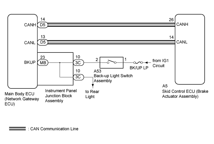
DTC C1494 Reverse Switch OFF Stuck |
DTC C1495 Reverse Switch ON Stuck |
| DTC No. | DTC Detection Condition | Trouble Area |
| C1494 | Back-up switch system circuit has a malfunction |
|
| C1495 | Back-up switch system circuit has a malfunction |
|
| 1.CHECK CAN COMMUNICATION SYSTEM |
Check if a CAN communication system DTC is output (Click here).
| Result | Proceed to |
| DTC is not output. | A |
| DTC is output. | B |
|
| ||||
| A | |
 |
| 2.READ VALUE USING GTS (MT REVERSE SW) |
Connect the GTS to the DLC3.
Turn the ignition switch to ON.
Select the Data List using the GTS.
| Tester Display | Measurement Item/Range | Normal Condition | Diagnostic Note |
| MT Reverse SW | Back-up light switch assembly status / ON or OFF | ON: Shift lever in R OFF: Shift lever not in R | - |
|
| ||||
| OK | |
|
| 3.RECONFIRM DTC OUTPUT |
Clear the DTCs (Click here).
Turn the ignition switch off.
Start the engine.
Drive the vehicle at a speed of 45 km/h (28 mph) or more for at least 120 seconds.
Check if the same DTC is output (Click here).
| Result | Proceed to |
| DTCs C1494 and/or C1495 are not output. | A |
| DTCs C1494 and/or C1495 are output. | B |
|
| ||||
| A | |
|
| 4.CHECK OPERATION |
Check the operation of the rear light.
|
| ||||
| OK | ||
 | ||
| ||
| 5.INSPECT BACK-UP LIGHT SWITCH ASSEMBLY |
Inspect the back-up light switch assembly (Click here).
|
| ||||
| OK | |
|
| 6.CHECK HARNESS AND CONNECTOR (BACK-UP LIGHT SWITCH ASSEMBLY POWER SOURCE TERMINAL) |
Disconnect the back-up light switch assembly connector.
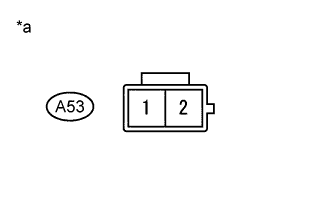 |
Measure the voltage according to the value(s) in the table below.
| Tester Connection | Switch Condition | Specified Condition |
| A53-1 - Body ground | Ignition Switch ON | 11 to 14 V |
| *a | Front view of wire harness connector (to Back-Up Light Switch Assembly) |
|
| ||||
| OK | |
|
| 7.CHECK HARNESS AND CONNECTOR (INSTRUMENT PANEL JUNCTION BLOCK - BACK-UP LIGHT SWITCH) |
Disconnect the instrument panel junction block assembly connector.
Disconnect the back-up light switch assembly connector.
Measure the resistance according to the value(s) in the table below.
| Tester Connection | Condition | Specified Condition |
| 3C-10 - A53-2 | Always | Below 1 Ω |
|
| ||||
| OK | |
|
| 8.INSPECT INSTRUMENT PANEL JUNCTION BLOCK ASSEMBLY |
Remove the instrument panel junction block assembly (Click here).
Remove the main body ECU (network gateway ECU) from the instrument panel junction block assembly .
Measure the resistance according to the value(s) in the table below.
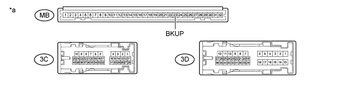
| *a | Component without harness connected (Instrument Panel Junction Block Assembly) | - | - |
| Tester Connection | Condition | Specified Condition |
| MB-23 (BKUP) - 3C-10 | Always | Below 1 Ω |
| MB-23 (BKUP) - 3D-4 | Always | Below 1 Ω |
| 3C-10 - 3D-4 | Always | Below 1 Ω |
| MB-23 (BKUP) - Body ground | Always | 10 kΩ or higher |
|
| ||||
| OK | ||
| ||
| ||

