FA20 ENGINE CONTROL IGNITION SYSTEM ON-VEHICLE INSPECTION
PROCEDURE

 1.PERFORM SPARK TEST
Check for DTCs (See page Engine / Hybrid System>FA20 (ENGINE CONTROL)>SFI SYSTEM>DTC CHECK / CLEAR).
- NOTICE:
-
If any DTC is present, perform troubleshooting in accordance with the procedure for that DTC.
Remove the 4 ignition coils and 4 spark plugs (See page Engine / Hybrid System>FA20 (ENGINE CONTROL)>IGNITION COIL AND SPARK PLUG>REMOVAL).
Hoist the engine assembly up with an engine sling device and a mini crane.
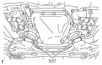
Remove the SST.
- SST
- 09250-53010
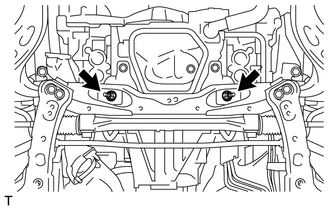
Install the 2 nuts.
- Torque:
- 60 N*m (612 kgf*cm, 44 ft.*lbf)
for Resin Intake Manifold:
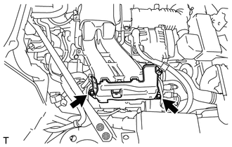
Remove the 2 bolts and injector cover (for bank 1).
for Aluminum Intake Manifold:
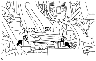
Remove the 2 bolts and disengage the 2 guides, and then remove the injector cover (for bank 1).
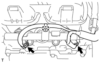
Disconnect the 2 fuel injector connectors.
for Resin Intake Manifold:
Install the injector cover (for bank 1) with the 2 bolts.
- Torque:
- 19 N*m (194 kgf*cm, 14 ft.*lbf)
for Aluminum Intake Manifold:
Engage the 2 guides and install the injector cover (for bank 1) with the 2 bolts.
- Torque:
- 19 N*m (194 kgf*cm, 14 ft.*lbf)
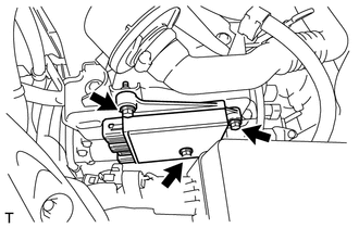
Install the injector driver with the 3 bolts.
- Torque:
- 6.4 N*m (65 kgf*cm, 57 in.*lbf)
- HINT:
-
Do not connect the upper side 2 connectors.
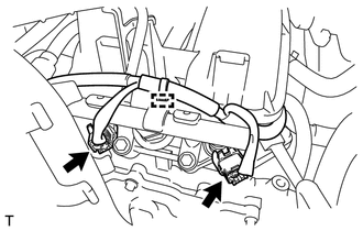
Disconnect the 2 fuel injector connectors.
Connect the cable to the negative battery terminal.
Install the air cleaner case sub-assembly with the hose.
Install a spark plug to each ignition coil and connect the ignition coil connector.
Ground the spark plug.
Check that spark occurs while the engine is being cranked.
Check whether sparks occur.
- NOTICE:
- ·
Ground the spark plugs when checking them.
·Do not crank the engine for more than 2 seconds.
·Do not use an ignition coil and spark plug that has been dropped or subjected to a strong impact.
·In vehicles with entry and start system, the cranking hold system means that if the engine does not start, then cranking is will continue for a specified time. To stop cranking, press the engine switch again.
If spark does not occur, perform the following procedure.
2.INSPECT IGNITION COIL AND SPARK PLUG
Perform the spark test in accordance with the following procedure.
Check that the wire harness side connector of the ignition coil assembly is securely connected.
- Result:
Result Proceed to NG Connect securely OK Go to next step
Perform a spark test on each ignition coil assembly.
If there is a cylinder where sparks do not occur, replace its ignition coil with the ignition coil of a cylinder where sparks occur normally.
Crank the engine and visually check that sparks occur at the cylinder with the normally operating ignition coil.
- Result:
Result Proceed to OK Replace ignition coil assembly NG Go to next step
Perform a spark test on each spark plug.
If there is a cylinder where sparks do not occur, replace its spark plug with the spark plug of a cylinder where sparks occur normally.
Crank the engine and visually check that sparks occur at the cylinder with the normally operating spark plug.
- Result:
Result Proceed to OK Replace spark plug NG Inspect the ignition system (See page (  ))
Disconnect the cable from the negative battery terminal.
Remove the air cleaner case sub-assembly with hose.
Remove the 3 bolts and the injector driver.
for Resin Intake Manifold:
Remove the 2 bolts and injector cover (for bank 1).
for Aluminum Intake Manifold:
Remove the 2 bolts and disengage the 2 guides, and then remove the injector cover (for bank 1).
Connect the 2 fuel injector connectors.
for Resin Intake Manifold:
Install the injector cover (for bank 1) with the 2 bolts.
- Torque:
- 19 N*m (194 kgf*cm, 14 ft.*lbf)
for Aluminum Intake Manifold:
Engage the 2 guides and install the injector cover (for bank 1) with the 2 bolts.
- Torque:
- 19 N*m (194 kgf*cm, 14 ft.*lbf)
Install the injector driver with the 3 bolts.
- Torque:
- 6.4 N*m (65 kgf*cm, 57 in.*lbf)
- HINT:
-
Do not connect the upper side 2 connectors.
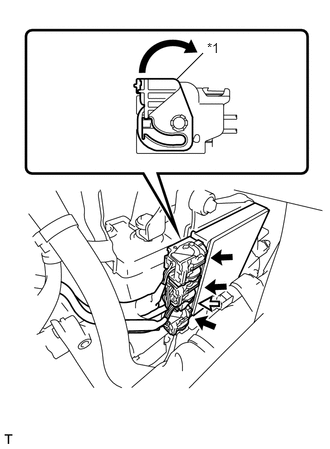
Connect the 4 connectors to the injector driver. Move the lock levers in the direction indicated by the arrow to lock the 3 connectors.
| *1 | Lock Lever |

|
Connector with Lock Lever |

|
Connector without Lock Lever |
Connect the 2 fuel injector connectors.
for Resin Intake Manifold:
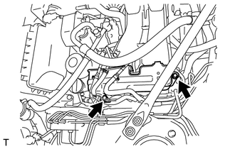
Install the injector cover (for bank 2) with the 2 bolts.
- Torque:
- 19 N*m (194 kgf*cm, 14 ft.*lbf)
for Aluminum Intake Manifold:
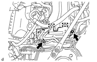
Engage the 2 guides and install the injector cover (for bank 2) with the 2 bolts.
- Torque:
- 19 N*m (194 kgf*cm, 14 ft.*lbf)
Remove the 2 nuts.
Hoist the engine assembly up with an engine sling device and a mini crane.
Install the SST.
- SST
- 09250-53010
Install the ignition coil assembly and spark plug (See page Engine / Hybrid System>FA20 (ENGINE CONTROL)>IGNITION COIL AND SPARK PLUG>INSTALLATION).
Clear the DTCs (See page Engine / Hybrid System>FA20 (ENGINE CONTROL)>SFI SYSTEM>DTC CHECK / CLEAR).
Check for DTCs (See page Engine / Hybrid System>FA20 (ENGINE CONTROL)>SFI SYSTEM>DTC CHECK / CLEAR).
- HINT:
-
Reinstall the sensors, connectors, etc. and restore the previous vehicle conditions before rechecking for DTCs.
19100P
3.INSPECT SPARK PLUG
- NOTICE:
- ·
When replacing a spark plug, make sure to use the designated spark plug because an ion current type misfire detection system is used for the spark plug.
·Do not damage the platinum tip. If the spark plug has been dropped, make sure to replace it with a designated new spark plug.
·Do not use a wire brush for cleaning.
·Do not attempt to adjust the electrode gap of a used spark plug.
·Make sure to use SST to check gaps, preventing the platinum tip from being damaged.
·If damaged, replace it with a designated new spark plug.
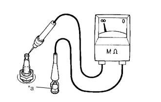
Check the electrode using a megohmmeter:
| *a | Ground |
Measure the resistance according to the value(s) in the table below.
- Standard Insulation Resistance:
Tester Connection Condition Specified Condition Spark plug (terminal part) - Body ground Always 10 MΩ or higher
- HINT:
- ·
If the result is not as specified, clean the spark plug with a spark plug cleaner and measure the resistance again.
·If a megohmmeter is not available, perform the following simple inspection instead.
Alternative inspection method:
Quickly accelerate the engine to 4000 rpm 5 times.
Remove the spark plug (See page Engine / Hybrid System>FA20 (ENGINE CONTROL)>IGNITION COIL AND SPARK PLUG>REMOVAL).
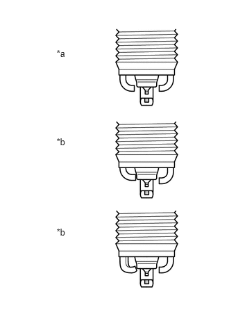
Visually check the spark plug.
If the electrode is dry, the spark plug is functioning properly. If the electrode is damp, proceed to the next step.
- HINT:
-
If a megohmmeter is not available, perform the following simple inspection instead.
| *a | Correct |
| *b | Incorrect |
Install the spark plug (See page Engine / Hybrid System>FA20 (ENGINE CONTROL)>IGNITION COIL AND SPARK PLUG>INSTALLATION).
Check the spark plug for any damage to its threads and insulator.
- HINT:
-
If there is any damage, replace the spark plug.
- Recommended Spark Plug:
Manufacturer Product DENSO made ZXE27HBR8
Reference:
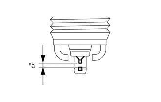
Using SST, check the spark plug electrode gap.
| *a | Spark Plug Electrode Gap |
- SST
- 09240-00020
- Maximum electrode gap for a used spark plug:
1.0 mm (0.0394 in.)
If the gap exceeds the maximum, replace the spark plug.
- NOTICE:
-
Never attempt to adjust the gap of a used plug.
- Electrode gap for a new spark plug:
0.7 to 0.8 mm (0.0276 to 0.0315 in.)
Clean the spark plugs.
If the electrode has traces of wet carbon, clean the electrode with a spark plug cleaner and then dry it.
- Standard air pressure:
588 kPa (6.0 kgf/cm2, 85 psi)
- Standard duration:
20 seconds or less
- HINT:
-
Only use a spark plug cleaner when the electrode is free of oil. If the electrode has traces of oil, use gasoline to clean off the oil before using the spark plug cleaner.