FA20 ENGINE CONTROL IGNITION COIL AND SPARK PLUG INSTALLATION
PROCEDURE

 19100P
1.INSTALL SPARK PLUG (for Bank 1)
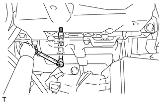
Install the 2 spark plugs onto the cylinder head sub-assembly.
- Torque:
- 17 N*m (173 kgf*cm, 13 ft.*lbf)
- NOTICE:
-
If a component has been dropped or subjected a strong impact, replace it.
19500
2.INSTALL IGNITION COIL ASSEMBLY (for Bank 1)
Install the 2 ignition coils onto the cylinder head cover sub-assembly with the 2 bolts.
- Torque:
- 8.5 N*m (87 kgf*cm, 75 in.*lbf)
- NOTICE:
-
If a component has been dropped or subjected a strong impact, replace it.
Connect the 2 ignition coil connectors to the ignition coil.
- NOTICE:
-
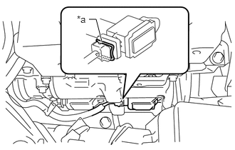 1.49,0.604 1.406,0.281 1.406,0.281 1.302,0.281 true 1.125,0.198 1.521,0.479 0.396,0.281 10 false *a
-
If a spring is used on the connector, make sure that the spring is back in the original position as shown in the illustration.
*a Spring
89871
3.INSTALL INJECTOR DRIVER
19100P
4.INSTALL SPARK PLUG (for Bank 2)
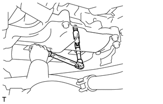
Install the 2 spark plugs onto the cylinder head sub-assembly.
- Torque:
- 17 N*m (173 kgf*cm, 13 ft.*lbf)
- NOTICE:
-
If a component has been dropped or subjected a strong impact, replace it.
19500
5.INSTALL IGNITION COIL ASSEMBLY (for Bank 2)
Install the 2 ignition coils onto the cylinder head cover sub-assembly with the 2 bolts.
- Torque:
- 8.5 N*m (87 kgf*cm, 75 in.*lbf)
- NOTICE:
-
If a component has been dropped or subjected a strong impact, replace it.
Connect the 2 ignition coil connectors to the ignition coil.
- NOTICE:
-
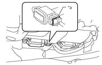 1.948,0.563 2.125,0.24 2.125,0.24 2.229,0.24 true 2.292,0.167 2.708,0.438 0.417,0.271 10 false *a
-
If a spring is used on the connector, make sure that the spring is back in the original position as shown in the illustration.
*a Spring
23261A
6.INSTALL INJECTOR COVER (for Bank 2)
Install the injector cover with the 2 bolts.
- Torque:
- 19 N*m (194 kgf*cm, 14 ft.*lbf)
Engage the clamp, and install the fuel hoses.
7.REMOVE SST
Hoist the engine assembly up with an engine sling device and a mini crane.
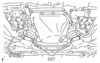
Remove the SST.
- SST
- 09250-53010
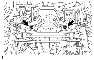
Install 2 new nuts.
- Torque:
- 60 N*m (612 kgf*cm, 44 ft.*lbf)
Remove the rope that is tying the front exhaust pipe sub-assembly to the front suspension cross member sub-assembly.
8.REMOVE ENGINE HANGER
17141
9.INSTALL EXHAUST MANIFOLD
31484A
10.INSTALL CLUTCH FLEXIBLE HOSE BRACKET (for RHD with Manual Transmission)
Install the clutch flexible hose bracket with the bolt.
- Torque:
- 7.5 N*m (76 kgf*cm, 66 in.*lbf)
Connect the clutch flexible tube with the clip.
82121
11.CONNECT ENGINE WIRE
Connect the engine wire with the wire harness clamp bracket mount bolt and 3 clamps.
- Torque:
- 11 N*m (112 kgf*cm, 8 ft.*lbf)
Connect the engine wire with the 4 clamps.
12.INSTALL AIR CLEANER CAP WITH AIR CLEANER HOSE
53608
13.INSTALL FRONT SUSPENSION UPPER TO COWL BRACE SUB-ASSEMBLY LH
53607
14.INSTALL FRONT SUSPENSION UPPER TO COWL BRACE SUB-ASSEMBLY RH
15.CONNECT CABLE TO NEGATIVE BATTERY TERMINAL