FA20 ENGINE MECHANICAL REAR CRANKSHAFT OIL SEAL INSTALLATION
PROCEDURE

 11401L
1.INSTALL REAR ENGINE OIL SEAL
Apply engine oil to the lip of a new rear engine oil seal.
- NOTICE:
-
Keep the lip free of foreign matter.
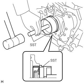
Using SST and a hammer, tap in the oil seal until its surface is flush with the rear oil seal retainer edge.
- SST
- 09223-15030
09950-70010 (09951-07150)
- Oil seal tap in depth:
0 to 1.0 mm (0 to 0.0394 in.)
- NOTICE:
- ·
Wipe any extra grease off of the crankshaft.
·Keep the lip free of foreign matter.
·Do not tap on the oil seal at an angle.
19315
2.INSTALL NO. 1 CRANKSHAFT POSITION SENSOR PLATE
Clean the 8 bolts and 8 bolt holes.
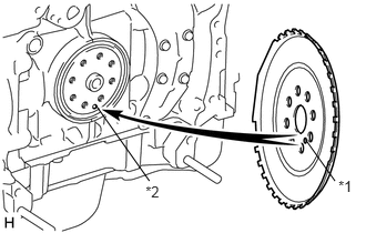
Install the No. 1 crankshaft position sensor plate.
| *1 | Pin Hole |
| *2 | Pin |
- HINT:
-
Align the pin of the front drive spacer with the pin hole of the crankshaft.
13405
3.INSTALL FLYWHEEL SUB-ASSEMBLY (for Manual Transmission)
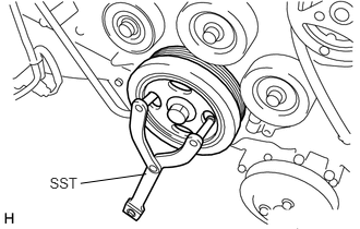
Using SST, hold the crankshaft pulley.
- SST
- 09960-10010 (09962-01000, 09963-01000)
Install the flywheel sub-assembly onto the crankshaft.
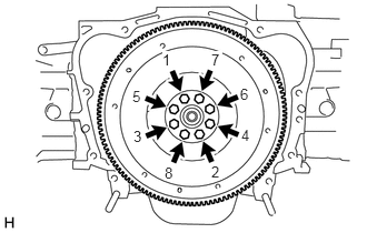
In several steps, uniformly install and tighten the 8 bolts in the sequence shown in the illustration.
- Torque:
- 85 N*m (867 kgf*cm, 63 ft.*lbf)
31250
4.INSTALL CLUTCH DISC ASSEMBLY (for Manual Transmission)
31210
5.INSTALL CLUTCH COVER ASSEMBLY (for Manual Transmission)
32101
6.INSTALL DRIVE PLATE AND RING GEAR SUB-ASSEMBLY (for Automatic Transmission)
Using SST, hold the crankshaft pulley.
- SST
- 09960-10010 (09962-01000, 09963-01000)
Install the drive plate and ring gear sub-assembly and rear drive plate spacer onto the crankshaft.
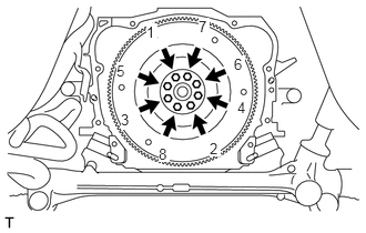
In several steps, uniformly install and tighten the 8 bolts in the sequence shown in the illustration.
- Torque:
- 95 N*m (969 kgf*cm, 70 ft.*lbf)
30300
7.REMOVE MANUAL TRANSMISSION ASSEMBLY (for Manual Transmission)
35000
8.INSTALL AUTOMATIC TRANSMISSION ASSEMBLY (for Automatic Transmission)
9.INSPECT FOR OIL LEAK