FA20 STARTING KEY INTER LOCK SYSTEM Key Cannot be Removed or Inserted
DESCRIPTION
When an ACC signal and a P signal is input, the control unit relay assembly outputs a signal to the key inter lock solenoid.
WIRING DIAGRAM
Refer to System Diagram (See page Engine / Hybrid System>FA20 STARTING>KEY INTER LOCK SYSTEM>SYSTEM DIAGRAM).
CAUTION / NOTICE / HINT
- NOTICE:
-
Inspect the fuses for circuits related to this system before performing the following inspection procedure.
PROCEDURE
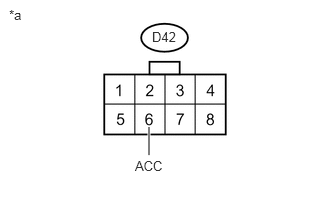
Disconnect the D42 control unit relay assembly connector.
Measure the voltage according to the value(s) in the table below.
- Standard Voltage:
Tester Connection Switch Condition Specified Condition D42-6 (ACC) - Body ground Ignition switch ON 11 to 14 V
| *a | Front view of wire harness connector
(to control unit relay assembly) |
OK
NG
Disconnect the D42 control unit relay assembly connector.
Measure the resistance according to the value(s) in the table below.
- Standard Resistance:
Tester Connection Condition Specified Condition D42-1 (E) - Body ground Always Below 1 Ω
OK
NG
Inspect the P switch (floor shift shift lever housing) (See page Drivetrain>TX6A (AUTOMATIC TRANSMISSION / TRANSAXLE)>SHIFT LEVER>INSPECTION).
OK
NG
Disconnect the D42 control unit relay assembly connector.
Disconnect the D28 P switch (floor shift shift lever housing) connector.
Measure the resistance according to the value(s) in the table below.
- Standard Resistance (Check for Open):
Tester Connection Condition Specified Condition D42-4 (P) - D28-1 (P) Always Below 1 Ω
- Standard Resistance (Check for Short):
Tester Connection Condition Specified Condition D42-4 (P) or D28-1 (P) - Body ground Always 10 kΩ or higher
OK
NG
Disconnect the D28 P switch (floor shift shift lever housing) connector.
Measure the resistance according to the value(s) in the table below.
- Standard Resistance:
Tester Connection Condition Specified Condition D28-3 (E) - Body ground Always Below 1 Ω
OK
NG
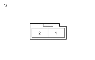
Disconnect the D60 key inter lock solenoid connector.
Measure the resistance according to the value(s) in the table below.
- Standard Resistance:
Tester Connection Condition Specified Condition 1 - 2 20°C (68°F) 13.05 to 15.95 Ω
| *a | Component without harness connected
(Key Inter Lock Solenoid) |
OK
NG
Disconnect the D42 control unit relay assembly connector.
Disconnect the D60 key inter lock solenoid connector.
Measure the resistance according to the value(s) in the table below.
- Standard Resistance (Check for Open):
Tester Connection Condition Specified Condition D42-5 (KLS+) - D60-2 Always Below 1 Ω
- Standard Resistance (Check for Short):
Tester Connection Condition Specified Condition D42-5 (KLS+) or D60-2 - Body ground Always 10 kΩ or higher
OK
NG
Disconnect the D60 key inter lock solenoid connector.
Measure the resistance according to the value(s) in the table below.
- Standard Resistance:
Tester Connection Condition Specified Condition D60-1 - Body ground Always Below 1 Ω
OK
NG