DOOR / HATCH LUGGAGE COMPARTMENT DOOR OPENER SYSTEM Luggage Compartment Door Opener does not Operate
DESCRIPTION
When the main body ECU (network gateway ECU) has received the ON signal from the luggage opening cancel switch assembly* and the luggage door opening switch assembly, the main body ECU (network gateway ECU) activates the luggage compartment door lock motor.
*: w/ Side Maker Light
WIRING DIAGRAM
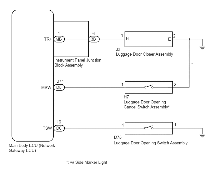
PROCEDURE
Connect the GTS to the DLC3.
Turn the ignition switch to ON.
Turn the GTS on.
Enter the following menus: Body Electrical / Main Body / Active Test.
Perform the Active Test according to the display on the GTS.
| Tester Display | Test Part | Control Range | Diagnostic Note |
|---|---|---|---|
| Trunk and Back-Door Open | Operate luggage compartment door lock motor | ON/OFF | This test will open the trunk |
- OK:
Luggage compartment door lock motor operates.
OK
NG
Check the vehicle specifications.
- Result:
Result Proceed to w/ Side Marker Light A w/o Side Marker Light B
A
B
When the luggage door opening cancel switch assembly is on, push the luggage door opening switch assembly and check that the luggage compartment door opens.
- OK:
Luggage compartment door opener system operates normally.
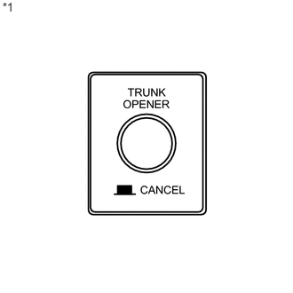
When the luggage door opening cancel switch assembly is off, push the luggage door opening switch assembly and check that the luggage compartment door does not open.
- OK:
Luggage compartment door opener system does not operate.
| *1 | Luggage Door Opening Cancel Switch Assembly |
- Result:
Result Proceed to NG A OK B
A
B
(See pageGeneral>INTRODUCTION>HOW TO TROUBLESHOOT ECU CONTROLLED SYSTEMS>HOW TO PROCEED WITH TROUBLESHOOTING)
Connect the GTS to the DLC3.
Turn the ignition switch to ON.
Turn the GTS on.
Enter the following menus: Body Electrical / Main Body / Data List.
Read the Data List according to the display on the GTS.
| Tester Display | Measurement Item/Range | Normal Condition | Diagnostic Note |
|---|---|---|---|
| Trunk/BDoor Open SW | Luggage door opening switch signal/ON or OFF | ON: Luggage door opening switch assembly is pushed
OFF: Luggage door opening switch assembly is not pushed |
- |
| Trunk Main SW | Luggage door opening cancel switch signal/ON or OFF | ON: Luggage door opening cancel switch assembly is pushed
OFF: Luggage door opening cancel switch assembly is not pushed |
- |
- OK:
On the GTS screen, each item changes between ON and OFF according to the above.
- Result:
Result Proceed to NG (Luggage door opening cancel switch assembly is abnormal) A NG (Luggage door opening switch assembly is abnormal) B OK C
A
B
C
Remove the luggage door opening cancel switch assembly (See page Vehicle Exterior>DOOR / HATCH>LUGGAGE COMPARTMENT DOOR OPENER MAIN SWITCH>REMOVAL).
Inspect the luggage door opening cancel switch assembly (See page Vehicle Exterior>DOOR / HATCH>LUGGAGE COMPARTMENT DOOR OPENER MAIN SWITCH>INSPECTION).
OK
NG
Disconnect the D5 main body ECU (network gateway ECU) connector and the H7 luggage door opening cancel switch assembly.
Measure the resistance according to the value(s) in the table below.
- Standard Resistance (Check for Open):
Tester Connection Condition Specified Condition D5-27 (TMSW) - H7-1 Always Below 1 Ω H7-2 - Body ground Always Below 1 Ω
- Standard Resistance (Check for Short):
Tester Connection Condition Specified Condition D5-27 (TMSW) - Body ground Always 10 kΩ or higher
OK
NG
Connect the GTS to the DLC3.
Turn the ignition switch to ON.
Turn the GTS on.
Enter the following menus: Body Electrical / Main Body / Data List.
Read the Data List according to the display on the GTS.
| Tester Display | Measurement Item/Range | Normal Condition | Diagnostic Note |
|---|---|---|---|
| Trunk/BDoor Open SW | Luggage door opening switch signal/ON or OFF | ON: Luggage door opening switch assembly is pushed
OFF: Luggage door opening switch assembly is not pushed |
- |
- OK:
On the GTS screen, each item changes between ON and OFF according to the above.
- Result:
Result Proceed to NG A OK B
A
B
Remove the luggage door opening switch assembly (See page Vehicle Exterior>DOOR / HATCH>LUGGAGE COMPARTMENT DOOR OPENER INNER SWITCH>REMOVAL).
Inspect the luggage door opening switch assembly (See page Vehicle Exterior>DOOR / HATCH>LUGGAGE COMPARTMENT DOOR OPENER INNER SWITCH>INSPECTION).
OK
NG
Disconnect the D6 main body ECU (network gateway ECU) connector and the D75 luggage door opening switch assembly.
Measure the resistance according to the value(s) in the table below.
- Standard Resistance (Check for Open):
Tester Connection Condition Specified Condition D6-16 (TSW) - D75-4 Always Below 1 Ω D75-1 - Body ground Always Below 1 Ω
- Standard Resistance (Check for Short):
Tester Connection Condition Specified Condition D6-16 (TSW) - Body ground Always 10 kΩ or higher
OK
NG
Remove the luggage door closer assembly (See page Vehicle Interior>DOOR LOCK>LUGGAGE COMPARTMENT DOOR LOCK>REMOVAL).
Inspect the luggage door closer assembly (See page Vehicle Interior>DOOR LOCK>LUGGAGE COMPARTMENT DOOR LOCK>INSPECTION).
OK
NG
Disconnect the 3B instrument panel junction block assembly connector and the J3 luggage door closer assembly.
Measure the resistance according to the value(s) in the table below.
- Standard Resistance (Check for Open):
Tester Connection Condition Specified Condition J3-1 (B) - 3B-6 Always Below 1 Ω J3-2 (E) - Body ground Always Below 1 Ω
- Standard Resistance (Check for Short):
Tester Connection Condition Specified Condition J3-1 (B) - Body ground Always 10 kΩ or higher
OK
NG
Temporarily replace the instrument panel junction block assembly with a new or normally functioning one (See page Power Source / Network>POWER DISTRIBUTION>MAIN BODY ECU>REMOVAL).
Check the luggage door closer assembly operation.
- OK:
Luggage door closer assembly operation is normal.
OK
NG