Home › Engine / Hybrid System › K3-VE ENGINE CONTROL › SFI SYSTEM › 2011.11–2015.08
RM19Y0E _51 Engine / Hybrid System _002967 K3-VE ENGINE CONTROL _0014971 SFI SYSTEM C

K3-VE ENGINE CONTROL  SFI SYSTEM  P0512  Starter Request Circuit  


DESCRIPTION

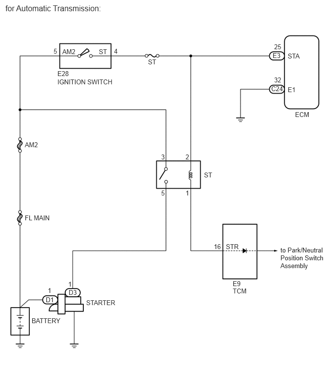
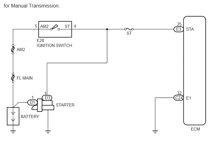
While the engine is being cranked, the battery voltage is applied to terminal STA of the ECM.

DTC No. Detection Item DTC Detection Condition Trouble Area MIL Memory
P0512 Starter Request Circuit Either of following condition met:
(1 trip detection logic)
·

Short in STA signal circuit for 31 seconds or more

·

Open in STA signal circuit when starting engine at vehicle speed of 0 km/h


·

Open or short in starter signal circuit

·

Open or short in speedometer circuit

·

ECM

·

TCM*

·

ST Relay*


Coems on DTC stored

*: for Automatic Transmission

WIRING DIAGRAM
A263066E03
0.688,3.792 1.969,4.229 1.281,0.438 10 BATTERY 0.99,3.323 1.635,3.75 0.646,0.427 10 D1 1.042,3.156 1.406,3.51 0.365,0.354 10 1 1.49,3.167 2.094,3.635 0.604,0.469 10 D3 1.469,3.021 1.958,3.458 0.49,0.438 10 1 1.854,3.406 2.99,3.719 1.135,0.313 10 STARTER 0.552,2.51 1.365,2.896 0.813,0.385 10 FL MAIN 0.552,1.563 1.271,2 0.719,0.438 10 AM2 1.333,0.792 1.979,1.198 0.646,0.406 10 AM2 2.146,0.792 2.75,1.156 0.604,0.365 10 ST 1.219,1.26 1.823,1.583 0.604,0.323 10 E28 1.219,1.427 2.833,1.906 1.615,0.479 10 IGNITION SWITCH 4.198,1.021 4.969,1.417 0.771,0.396 10 ST 5.844,0.885 6.49,1.313 0.646,0.427 10 E3 5.875,0.719 6.448,1.167 0.573,0.448 10 25 5.813,3.167 6.271,3.458 0.458,0.292 10 C24 5.875,3.01 6.271,3.302 0.396,0.292 10 32 6.177,0.885 6.74,1.24 0.563,0.354 10 STA 6.177,3.177 6.646,3.542 0.469,0.365 10 E1 6.333,4.208 6.948,4.563 0.615,0.354 10 ECM 1.156,0.781 1.656,1.167 0.5,0.385 10 5 2.448,0.781 2.917,1.208 0.469,0.427 10 4 0.125,0.083 2.531,0.625 2.406,0.542 12 for Manual Transmission:

A263065E05
0.677,6.771 1.729,7.156 1.052,0.385 10 BATTERY 0.979,6.323 1.448,6.688 0.469,0.365 10 D1 1.021,6.125 1.375,6.438 0.354,0.313 10 1 1.469,6.167 1.99,6.573 0.521,0.406 10 D3 1.458,5.99 2.104,6.479 0.646,0.49 10 1 1.844,6.385 3.135,6.896 1.292,0.51 10 STARTER 0.531,4.573 1.375,4.958 0.844,0.385 10 FL MAIN 0.531,3.01 1.469,3.667 0.938,0.656 10 AM2 1.333,1.021 1.938,1.448 0.604,0.427 10 AM2 2.115,1.021 2.635,1.385 0.521,0.365 10 ST 1.229,1.49 1.76,1.885 0.531,0.396 10 E28 1.229,1.667 2.74,2.094 1.51,0.427 10 IGNITION SWITCH 3.167,1.24 3.75,1.594 0.583,0.354 10 ST 4.365,3.656 5.125,4 0.76,0.344 10 ST 4.573,5.188 5.083,5.573 0.51,0.385 10 16 5.833,1.104 6.323,1.469 0.49,0.365 10 E3 5.865,0.917 6.292,1.281 0.427,0.365 10 25 5.802,1.813 6.406,2.167 0.604,0.354 10 C24 5.865,1.625 6.313,1.958 0.448,0.333 10 32 4.833,5.188 5.417,5.563 0.583,0.375 10 STR 6.156,1.115 6.583,1.406 0.427,0.292 10 STA 6.156,1.833 6.5,2.135 0.344,0.302 10 E1 6.313,2.365 6.802,2.698 0.49,0.333 10 ECM 1.146,1.01 1.5,1.365 0.354,0.354 10 5 2.438,1.01 2.802,1.354 0.365,0.344 10 4 3.448,3.271 3.781,3.583 0.333,0.313 10 3 3.448,4.042 3.802,4.354 0.354,0.313 10 5 3.969,3.271 4.323,3.604 0.354,0.333 10 2 3.969,4.042 4.292,4.344 0.323,0.302 10 1 0.115,0.073 2.823,0.823 2.708,0.75 12 for Automatic Transmission: 6,5.26 7.104,6.156 1.104,0.896 10 to Park/Neutral Position Switch Assembly 4.979,6.135 5.625,6.531 0.646,0.396 10 TCM 4.979,5.979 5.531,6.323 0.552,0.344 10 E9

Refer to DTC P0500 (See page Engine / Hybrid System>K3-VE ENGINE CONTROL>SFI SYSTEM>P0500).

CAUTION / NOTICE / HINT

NOTICE:

Inspect the fuses for circuits related to this system before performing the following procedure.


HINT:

This diagnostic flowchart is based on the premise that the engine is cranked normally. If the engine does not crank, proceed to the Problem Symptoms Table (See page Engine / Hybrid System>K3-VE ENGINE CONTROL>SFI SYSTEM>PROBLEM SYMPTOMS TABLE).


PROCEDURE
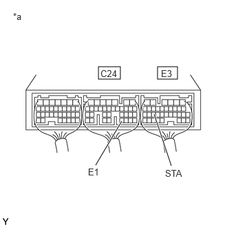
1.INSPECT ECM (STA VOLTAGE)
a.
A141531C17
1.49,1.01 1.823,1.198 0.333,0.188 2.385,1.01 2.688,1.198 0.302,0.188 1.448,2.5 1.844,1.833 true 2.594,2.51 2.333,1.729 true 1.333,2.521 1.844,2.917 0.51,0.396 10 E1 0.198,0.167 0.583,0.531 0.385,0.365 10 *a 2.5,2.542 3.042,2.865 0.542,0.323 10 STA 1.521,1.031 1.979,1.385 0.458,0.354 10 C24 2.438,1.031 2.875,1.344 0.438,0.313 10 E3
*a Component with harness connected
(ECM)


Turn the ignition switch to ON.


b.

Measure the voltage according to the value(s) in the table below.

Standard Voltage:
Tester Connection Switch Condition Specified Condition
E3-25 (STA) - C24-32 (E1) Ignition switch ON 0 V
E3-25 (STA) - C24-32 (E1) Engine cranking 6 V or more


Result:
Proceed to
OK
NG


OK

NG

2.CHECK AND REPLACE HARNESS AND CONNECTOR (ECM - IGNITION SWITCH)
a.

Disconnect the ECM connector.


b.

Disconnect the ignition switch connector.


c.

Measure the resistance according to the value(s) in the table below.

Standard Resistance (Check for Open):
Tester Connection Condition Specified Condition
E3-25 (STA) - E28-4 (ST) Always Below 1 Ω


Standard Resistance (Check for Short):
Tester Connection Condition Specified Condition
E3-25 (STA) or E28-4 (ST) - Body ground Always 10 kΩ or higher


d.

Disconnect the ignition switch connector.


e.

Reconnect the ECM connector.

Result:
Proceed to
OK
NG


OK

3.INSPECT IGNITION SWITCH

NG

REPAIR OR REPLACE HARNESS OR CONNECTOR

3.INSPECT IGNITION SWITCH
a.

Inspect the ignition switch.

Click hereEngine / Hybrid System>K3-VE STARTING>IGNITION SWITCH>INSPECTION

Result:
Proceed to
A
B
C


A

4.INSPECT RELAY (ST RELAY)

B

8.CHECK HARNESS AND CONNECTOR (IGNITION SWITCH - STARTER)

C

4.INSPECT RELAY (ST RELAY)
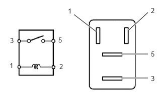
a.
A167865N15
1.99,0.656 1.531,0.302 true 2.656,0.635 3.063,0.26 true 2.531,1.125 3.063,1.125 true 2.521,1.625 3.063,1.625 true 1.208,0.75 1.49,1.021 0.281,0.271 10 5 0.208,0.76 0.51,1.031 0.302,0.271 10 3 1.229,1.302 1.521,1.615 0.292,0.313 10 2 0.198,1.281 0.51,1.573 0.313,0.292 10 1 1.406,0.146 1.781,0.469 0.375,0.323 10 1 3.125,0.135 3.406,0.417 0.281,0.281 10 2 3.125,1.552 3.385,1.813 0.26,0.26 10 3 3.125,1.042 3.427,1.396 0.302,0.354 10 5

Remove the ST relay from the fuse block.


b.

Measure the resistance according to the value(s) in the table below.

Standard Resistance:
Tester Connection Condition Specified Condition
3 - 5 No battery voltage applied to terminals 1 and 2 10 kΩ or higher
3 - 5 Battery voltage applied to terminals 1 and 2 Below 1 Ω


c.

Reinstall the ST relay.

Result:
Proceed to
OK
NG


OK

5.CHECK HARNESS AND CONNECTOR (ST RELAY - TCM)

NG

REPLACE RELAY

5.CHECK HARNESS AND CONNECTOR (ST RELAY - TCM)
a.

Remove the ST relay from the fuse block.


b.

Disconnect the TCM connector.


c.

Measure the resistance according to the value(s) in the table below.

Standard Resistance (Check for Open):
Tester Connection Condition Specified Condition
Starter relay (1) - E9-16 (STR) Always Below 1 Ω


Standard Resistance (Check for Short):
Tester Connection Condition Specified Condition
Starter relay (1) or E9-16 (STR) - Body ground Always 10 kΩ or higher


d.

Reconnect the TCM connector.


e.

Reinstall the ST relay.

Result:
Proceed to
OK
NG


OK

6.CHECK HARNESS AND CONNECTOR (IGNITION SWITCH - ST RELAY)

NG

REPAIR OR REPLACE HARNESS OR CONNECTOR

6.CHECK HARNESS AND CONNECTOR (IGNITION SWITCH - ST RELAY)
a.

Disconnect the ignition switch connector.


b.

Remove the ST relay from the fuse block.


c.

Measure the resistance according to the value(s) in the table below.

Standard Resistance (Check for Open):
Tester Connection Condition Specified Condition
E28-4 (ST) - ST relay (2) Always Below 1 Ω


Standard Resistance (Check for Short):
Tester Connection Condition Specified Condition
E28-4 (ST) or ST relay (2) - Body ground Always 10 kΩ or higher


d.

Reinstall the ST relay.


e.

Reconnect the ignition switch connector.

Result:
Proceed to
OK
NG


OK

7.INSPECT PARK / NEUTRAL POSITION SWITCH CIRCUIT

NG

REPAIR OR REPLACE HARNESS OR CONNECTOR

7.INSPECT PARK / NEUTRAL POSITION SWITCH CIRCUIT
HINT:

Refer to Automatic Transmission System / DTC P0705 procedure.

Click hereDrivetrain>A4Q AUTOMATIC TRANSMISSION / TRANSAXLE>AUTOMATIC TRANSMISSION SYSTEM>P0705


Result:
Result Proceed to
NG A
OK (for LHD) B
OK (for RHD) C


A

REPAIR OR REPLACE PARK / NEUTRAL POSITION SWITCH CIRCUIT

B

C

8.CHECK HARNESS AND CONNECTOR (IGNITION SWITCH - STARTER)
a.

Disconnect the ignition switch connector.


b.

Disconnect the starter connector.


c.

Measure the resistance according to the value(s) in the table below.

Standard Resistance (Check for Open):
Tester Connection Condition Specified Condition
E28-4 (ST) - D3-1 Always Below 1 Ω


Standard Resistance (Check for Short):
Tester Connection Condition Specified Condition
E28-4 (ST) or D3-1 - Body ground Always 10 kΩ or higher


d.

Reconnect the starter connector.


e.

Reconnect the ignition switch connector.

Result:
Result Proceed to
NG A
OK (for LHD) B
OK (for RHD) C


A

REPAIR OR REPLACE HARNESS OR CONNECTOR

B

C