3SZ-VE ENGINE MECHANICAL VALVE CLEARANCE ADJUSTMENT
PROCEDURE

 17881
1.REMOVE NO. 1 AIR CLEANER HOSE
17700
2.REMOVE AIR CLEANER ASSEMBLY
19500
3.REMOVE IGNITION COIL ASSEMBLY
12261
4.DISCONNECT VENTILATION HOSE
12262
5.REMOVE NO. 2 VENTILATION HOSE
22268
6.REMOVE NO. 2 THROTTLE BODY BRACKET
7.SEPARATE ENGINE WIRE
16507
8.SEPARATE RADIATOR PIPE SUB-ASSEMBLY
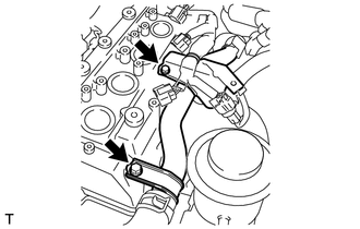
Remove the 2 bolts, then disconnect the radiator pipe sub-assembly.
11201
9.REMOVE CYLINDER HEAD COVER SUB-ASSEMBLY
10.INSPECT VALVE CLEARANCE
- NOTICE:
-
Inspect the valve clearance when the engine is cold.
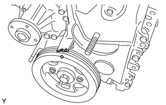
Set the No. 1 cylinder to the TDC/compression.
Turn the crankshaft clockwise, to align the timing mark of the crankshaft pulley with the indicator of the timing chain cover.
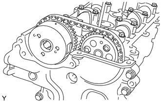
Check that the matchmarks of the camshaft timing sprockets are facing upward. If not, turn the crankshaft 1 revolution so they face upward.
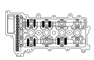
Inspect the valve clearance indicated in the illustration.
Using a feeler gauge, measure the clearance between the valve lifter and camshaft.
- Valve clearance (Cold):
Intake 0.15 to 0.23 mm (0.0059 to 0.0091 in.)
Exhaust 0.28 to 0.36 mm (0.0110 to 0.0142 in.)
- HINT:
-
If the clearance is not as specified, record the out-of-specification measurement.
Turn the crankshaft clockwise 1 complete revolution and set the No. 4 cylinder to the TDC/compression.
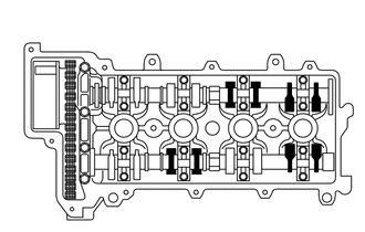
Inspect the valve clearance indicated in the illustration.
Using a feeler gauge, measure the clearance between the valve lifter and camshaft.
- Valve clearance (Cold):
Intake 0.15 to 0.23 mm (0.0059 to 0.0091 in.)
Exhaust 0.28 to 0.36 mm (0.0110 to 0.0142 in.)
- HINT:
-
If the clearance is not as specified, record the out-of-specification measurement.
11.ADJUST VALVE CLEARANCE
- NOTICE:
-
In order to prevent interference of the valve with the piston when removing the camshaft, turn the crankshaft in the engine cranking direction by approximately 90° from the TDC/compression of the NO. 1 cylinder.
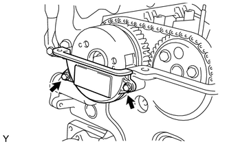
Remove the 2 bolts and No. 2 timing chain or belt cover.
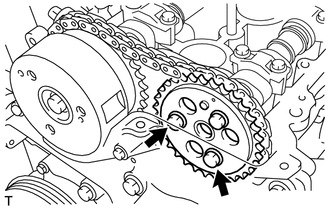
Turn the crankshaft pulley clockwise and remove 2 of the 3 bolts.
Turn the crankshaft clockwise, to align the timing mark of the crankshaft pulley with the indicator of the timing chain cover.
Check that the matchmarks of the camshaft timing sprocket are facing upward. If not, turn the crankshaft 1 revolution so they face upward (No. 1 cylinder at TDC/compression).
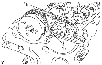
| *a | Paint Mark |
| *b | Matchmark |
Put paint marks on the timing chain plates which align with the matchmarks of the camshaft timing sprocket and camshaft timing gear.
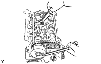
While holding the hexagonal lobe of the camshaft, loosen the bolt which holds the camshaft timing sprocket.
- NOTICE:
-
The bolt should be only loosened. Do not remove the bolt and sprocket.
- HINT:
-
Loosen the bolt in advance. If the bolt is loosened after the chain is removed, the chain may interfere with the sprocket.
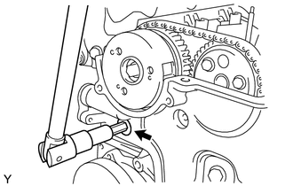
Using a 10 mm socket hexagon wrench, remove the chain cover service hole screw plug.
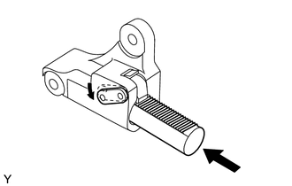
Insert a screwdriver into the chain cover service hole, then move the stopper plate of the tensioner downward and keep it unlocked.
- HINT:
- ·
This operation unlocks the plunger of the tensioner.
·If the stopper plate is not unlocked easily, turn the camshaft right and left using the hexagonal lobe of the camshaft.
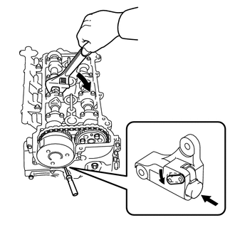
Using the hexagonal lobe of the camshaft, slightly turn the camshaft to the right so the plunger of the tensioner is pushed by the chain.
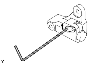
Remove the screwdriver from the chain cover service hole. Align the holes of the stopper plate and tensioner, and insert a 2.5 mm (0.098 in.) diameter hexagon wrench.
- NOTICE:
- ·
Hold the camshaft using the hexagonal lobe of the camshaft.
·Hold the 2.5 mm (0.098 in.) diameter hexagon wrench with tape so it is not pulled out.
- HINT:
-
This operation keeps the plunger of the tensioner in place.
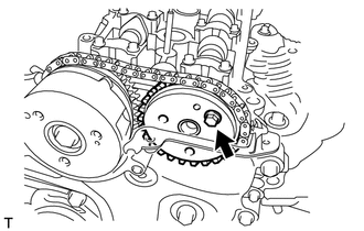
Remove the remaining bolt, then remove the camshaft timing sprocket.
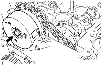
Remove the bolt and remove the camshaft timing sprocket assembly.
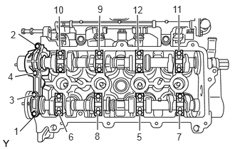
Remove the 20 bolts.
Remove the No. 1 bearing cap and 8 No. 2 bearing caps in the sequence shown in the illustration.
Hold the timing chain by hand, then remove the camshafts.
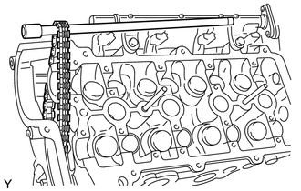
After removing the camshafts, hold the chain by inserting a bar to prevent it from coming off.
Remove the valve lifters.
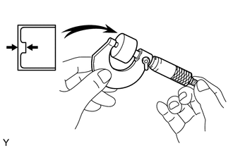
Using a micrometer, measure the thickness of the removed valve lifters.
Calculate the thickness of the valve lifters so that the valve clearance comes within the specified values.
- Specified value (Cold):
Intake A = B + (C - 0.18 mm (0.0071 in.))
Exhaust A = B + (C - 0.31 mm (0.0122 in.))
| A | Selected valve lifter |
| B | Thickness of removed valve lifter |
| C | Measured valve clearance |
Select a new lifter with a thickness as close to the calculated values as possible.
- HINT:
- ·
The lifters are available in 29 sizes in increments of 0.02 mm (0.0008 in.), from 5.12 mm (0.2016 in.) to 5.68 mm (0.2236 in.).
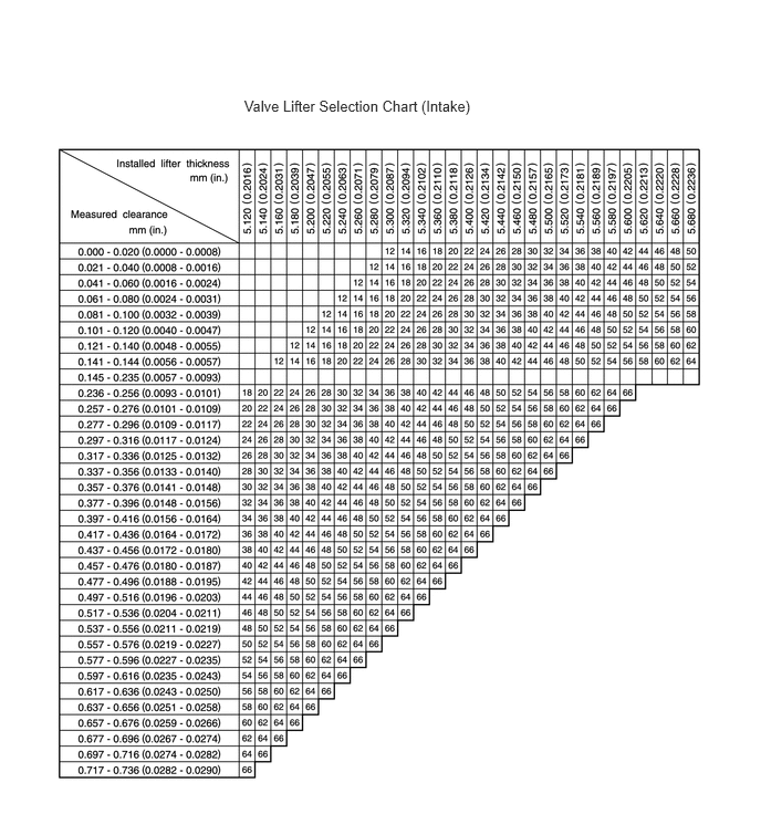
- Intake valve clearance (Cold):
0.15 to 0.23 mm (0.0059 to 0.0091 in.)
- EXAMPLE:
The 5.250 mm (0.2067 in.) lifter is installed, and the measured clearance is 0.400 mm (0.0158 in.).
Replace the 5.250 mm (0.2067 in.) lifter with a new No. 48 lifter.
- New Lifter Thickness:
Lifter No. Thickness Lifter No. Thickness Lifter No. Thickness 12 5.120 (00002016) 32 5.320 (0.2094) 52 5.520 (0.2173) 14 5.140 (0.2024) 34 5.340 (0.2102) 54 5.540 (0.2181) 16 5.160 (0.2031) 36 5.360 (0.2110) 56 5.560 (0.2189) 18 5.180 (0.2039) 38 5.380 (0.2118) 58 5.580 (0.2197) 20 5.200 (0.2047) 40 5.400 (0.2126) 60 5.600 (0.2205) 22 5.220 (0.2055) 42 5.420 (0.2134) 62 5.620 (0.2213) 24 5.240 (0.2063) 44 5.440 (0.2142) 64 5.640 (0.2220) 26 5.260 (0.2071) 46 5.460 (0.2150) 66 5.660 (0.2228) 28 5.280 (0.2079) 48 5.480 (0.2157) 68 5.680 (0.2236) 30 5.300 (0.2087) 50 5.500 (0.2165) - -
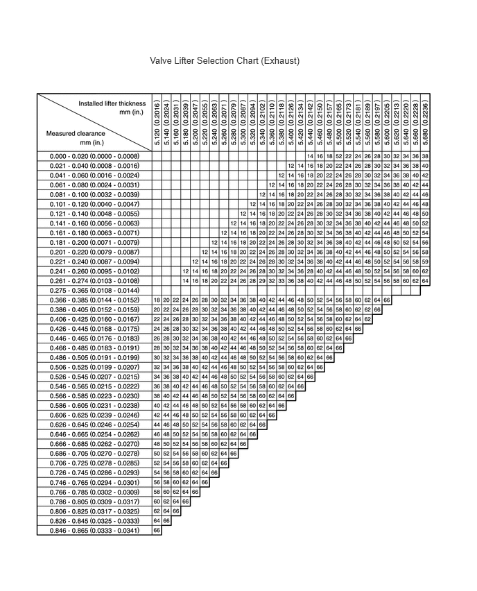
- Exhaust valve clearance (Cold):
0.28 to 0.36 mm (0.0110 to 0.0142 in.)
- EXAMPLE:
The 5.340 mm (0.2102 in.) lifter is installed, and the measured clearance is 0.440 mm (0.0173 in.).
Replace the 5.340 mm (0.2102 in.) lifter with a new No. 48 lifter.
- New Lifter Thickness:
Lifter No. Thickness Lifter No. Thickness Lifter No. Thickness 12 5.120 (00002016) 32 5.320 (0.2094) 52 5.520 (0.2173) 14 5.140 (0.2024) 34 5.340 (0.2102) 54 5.540 (0.2181) 16 5.160 (0.2031) 36 5.360 (0.2110) 56 5.560 (0.2189) 18 5.180 (0.2039) 38 5.380 (0.2118) 58 5.580 (0.2197) 20 5.200 (0.2047) 40 5.400 (0.2126) 60 5.600 (0.2205) 22 5.220 (0.2055) 42 5.420 (0.2134) 62 5.620 (0.2213) 24 5.240 (0.2063) 44 5.440 (0.2142) 64 5.640 (0.2220) 26 5.260 (0.2071) 46 5.460 (0.2150) 66 5.660 (0.2228) 28 5.280 (0.2079) 48 5.480 (0.2157) 68 5.680 (0.2236) 30 5.300 (0.2087) 50 5.500 (0.2165) - -
Install the selected valve lifter.
Apply engine oil to the cam, cylinder head journal, and top of the valve lifter.
Set the camshafts so the cam lobes of the No. 3 and No. 4 cylinders on the intake side (the camshaft) push the valve lifters, and the cam lobes of the No. 2 and No. 4 cylinders on the exhaust side (the camshaft No. 2) push the valve lifters.
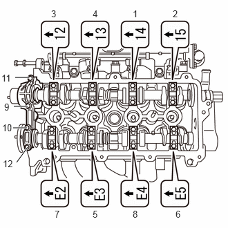
Examine the front marks and numbers and check that the sequence order is as shown in the illustration. Then tighten the bolts in several steps in the sequence shown in the illustration.
- Torque:
- 13 N*m (133 kgf*cm, 10 ft.*lbf)
Temporarily install the camshaft timing sprocket with the bolt.
Temporarily install the No. 2 camshaft sprocket with one bolt.
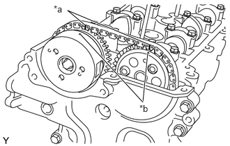
| *a | Paint Mark |
| *b | Matchmark |
Install the chain so the matchmarks of the camshaft timing sprockets and the paint marks, which were marked before removing the chain, are aligned.
- HINT:
-
First, install the chain onto either of the camshafts. Turn the camshaft to the right and left using the hexagonal lobe of the camshaft so the match marks of the sprockets and the paint marks of the chain are aligned.
Remove the 2.5 mm (0.098 in.) diameter hexagon wrench from the tensioner.
- HINT:
-
Using the hexagonal lobe of the camshaft, slightly turn the camshaft to the left, then remove the 2.5 mm (0.098 in.) diameter hexagon wrench with the chain loose on the tensioner side.
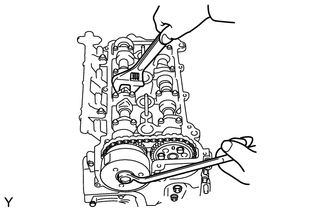
While holding the hexagonal lobe of the camshaft, tighten the bolt, which installs the camshaft timing sprocket, to the specified torque.
- Torque:
- 47 N*m (479 kgf*cm, 35 ft.*lbf)
Apply adhesive to 2 or 3 threads of the chain cover service hole screw plug bolt end.
- NOTICE:
-
Remove any oil from the bolts and bolt holes.
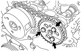
Turn the crankshaft pulley clockwise and install the remaining 2 bolts to the No. 2 camshaft sprocket. Then tighten all 3 bolts to the specified torque.
- Torque:
- 8.0 N*m (82 kgf*cm, 71 in.*lbf)
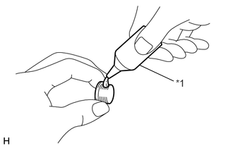
| *1 | Adhesive |
Apply adhesive to the 2 or 3 threads of the chain cover service hole screw plug bolt end.
- NOTICE:
-
Keep the bolt and bolt hole free of foreign matter and oil.
Using a 10 mm socket hexagon wrench, install the chain cover service hole screw plug.
- Torque:
- 17 N*m (168 kgf*cm, 12 ft.*lbf)
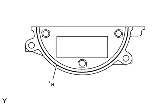
| *a | Seal Packing |
Install the No. 2 timing chain or belt cover.
Apply seal packing as illustrated.
- Seal packing:
Toyota Genuine Seal Packing Black, Three Bond 1207B or equivalent
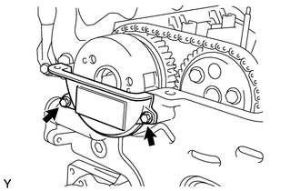
Install the No. 2 timing chain or belt cover with the 2 bolts.
- Torque:
- 8.5 N*m (87 kgf*cm, 75 in.*lbf)
- NOTICE:
- ·
Remove any oil from the contact surface.
·Install No. 2 timing chain cover within 3 minutes of applying the seal packing.
·Do not start the engine for at least 2 hours after the installation.
11201
12.INSTALL CYLINDER HEAD COVER SUB-ASSEMBLY
16507
13.INSTALL RADIATOR PIPE SUB-ASSEMBLY
14.INSTALL ENGINE WIRE
22268
15.INSTALL NO. 2 THROTTLE BODY BRACKET
19500
16.INSTALL IGNITION COIL ASSEMBLY
12262
17.INSTALL NO. 2 VENTILATION HOSE
12261
18.INSTALL VENTILATION HOSE
17700
19.INSTALL AIR CLEANER ASSEMBLY
17881
20.INSTALL NO. 1 AIR CLEANER HOSE
21.INSPECT FOR ENGINE OIL LEAK