3SZ-VE ENGINE MECHANICAL ENGINE ASSEMBLY INSTALLATION
CAUTION / NOTICE / HINT
- NOTICE:
-
As the engine assembly with transmission is extremely heavy, the engine lifter may suddenly drop if the instructions listed in the repair manual are not followed. Therefore, always follow the instructions listed in the repair manual when performing this procedure.
PROCEDURE

 11355
1.INSTALL REAR END PLATE
Install the rear end plate with the bolt.
- Torque:
- 7.5 N*m (77 kgf*cm, 66 in.*lbf)
32101
2.INSTALL DRIVE PLATE AND RING GEAR SUB-ASSEMBLY (for Automatic Transmission)
Hold the crankshaft pulley with SST.
- SST
- 09330-00021
09213-54015 (91651-60855)
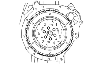
Install the drive plate and ring gear sub-assembly with the 6 bolts.
- Torque:
- 78 N*m (795 kgf*cm, 58 ft.*lbf)
13405
3.INSTALL FLYWHEEL SUB-ASSEMBLY (for Manual Transmission)
Hold the crankshaft pulley with SST.
- SST
- 09330-00021
09213-54015 (91651-60855)
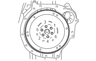
Install the flywheel sub-assembly and flywheel spacer ring with the 6 bolts.
- Torque:
- 78 N*m (795 kgf*cm, 58 ft.*lbf)
31250
4.INSTALL CLUTCH DISC ASSEMBLY (for Manual Transmission)
31210
5.INSTALL CLUTCH COVER ASSEMBLY (for Manual Transmission)
35000
6.INSTALL AUTOMATIC TRANSMISSION ASSEMBLY (for Automatic Transmission)
33030
7.INSTALL MANUAL TRANSMISSION ASSEMBLY (for Manual Transmission)
8.INSTALL STARTER ASSEMBLY
9.INSTALL OIL COOLER TUBE SUB-ASSEMBLY (for Automatic Transmission)
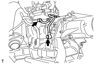
Install the oil cooler tube sub-assembly with the 2 union bolts and 2 new gasket.
- Torque:
- 34 N*m (350 kgf*cm, 25 ft.*lbf)
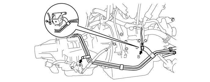
Install the 2 oil cooler tube bracket bolts.
- Torque:
- Bolt A, B : 8.4 N*m (85 kgf*cm, 74 in.*lbf)
51201
10.INSTALL FRONT SUSPENSION CROSSMEMBER SUB-ASSEMBLY
Using an engine sling device and a chain block, install the engine assembly into the vehicle.
Install the 2 engine mounting insulator with the 4 bolts and 2 nuts.
- Torque:
- bolt : 34 N*m (347 kgf*cm, 25 ft.*lbf)
- nut : 48 N*m (490 kgf*cm, 36 ft.*lbf)
11.INSTALL ENGINE WIRE
Connect all of the clamps and connectors and install the engine wire to the engine assembly.
12.REMOVE ENGINE HANGER
Remove the 2 bolts and 2 engine hangers.
13.INSTALL ENGINE AND TRANSMISSION ASSEMBLY
Set the engine lifter.
Operate the engine lifer, and then temporarily install the engine assembly with transmission and the front suspension cross member sub-assembly to the vehicle with the 4 bolts.
- CAUTION:
-
Do not raise the engine more than necessary. If the engine is raised excessively, the vehicle may also be lifted up.
- NOTICE:
- ·
Make sure that the engine is clear of all wiring and hoses.
- ·
While raising the engine into the vehicle, do not allow it to contact the vehicle.
- Torque:
- 125 N*m (1275 kgf*cm, 92 ft.*lbf)
Install the rear engine support member sub-assembly with the 6 bolts.
- Torque:
- 39 N*m (398 kgf*cm, 29 ft.*lbf)
51202D
14.INSTALL FRONT LOWER SUSPENSION CROSSMEMBER SUB-ASSEMBLY
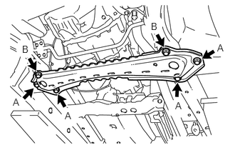
Install the front lower suspension crossmember sub-assembly with the 4 bolts.
- Torque:
- Bolt A : 110 N*m (1120 kgf*cm, 81 ft.*lbf)
Install the front lower suspension crossmember sub-assembly with the 2 new bolts.
- Torque:
- Bolt B : 100 N*m (1020 kgf*cm, 74 ft.*lbf)
15.CONNECT CONNECTOR (for Automatic Transmission)
Connect the solenoid wire connector.
Connect the park/neutral position switch connector.
Connect the input speed connector.
Connect the output speed sensor connector.
16.CONNECT CONNECTOR (for Manual Transmission)
Connect the back-up light switch connector and the wire harness clamp.
Connect the speedometer sensor connector and the wire harness clamp. (w/o ABS)
17.CONNECT TRANSMISSION CONTROL CABLE ASSEMBLY (for Automatic Transmission)
18.CONNECT TRANSMISSION CONTROL CABLE ASSEMBLY (for Manual Transmission)
Connect the 2 cables and install the 2 clips and washer.
Install 2 new clips onto the control cable bracket.
17410
19.INSTALL FRONT EXHAUST PIPE ASSEMBLY
20.INSTALL PROPELLER SHAFT ASSEMBLY
21.INSTALL FRONT AXLE ASSEMBLY LH
Install the front axle assembly LH with the 2 boles and 2 nuts.
- Torque:
- 128 N*m (1300 kgf*cm, 94 ft.*lbf)
22.INSTALL FRONT AXLE ASSEMBLY RH
- HINT:
-
Use the same procedures described for the LH side.
89543
23.INSTALL FRONT SPEED SENSOR LH (w/ ABS)
89542
24.INSTALL FRONT SPEED SENSOR RH (w/ ABS)
- HINT:
-
Use the same procedures described for the LH side.
25.INSTALL FRONT DISC BRAKE CALIPER ASSEMBLY LH
26.INSTALL FRONT DISC BRAKE CALIPER ASSEMBLY RH
- HINT:
-
Use the same procedures described for the LH side.
48824
27.INSTALL FRONT STABILIZER BRACKET
48820
28.INSTALL FRONT STABILIZER LINK ASSEMBLY
Install the front stabilizer link assembly with new nut.
- Torque:
- 74 N*m (755 kgf*cm, 55 ft.*lbf)
- HINT:
- ·
If the ball joint turns together with the nut, use a socket hexagon wrench 6 to hold the stud.
·The installation procedure for the RH side is the same as that for the LH side.
29.INSTALL CLUTCH RELEASE CYLINDER ASSEMBLY (for Manual Transmission)
Install the clutch release cylinder assembly with the 2 bolts.
- Torque:
- 18 N*m (185 kgf*cm, 13 ft.*lbf)
30.INSTALL STEERING INTERMEDIATE SHAFT ASSEMBLY
87246X
31.INSTALL HEATER WATER HOSE (w/ Heater)
Connect the heater water hose to the No. 1 radiator pipe sub-assembly.
16261
32.INSTALL WATER BY-PASS HOSE (w/ Heater)
Connect the water by-pass hose to the water hose joint.
33.INSTALL FUEL TUBE SUB-ASSEMBLY
Attach the gray colored release button of the tube sub-assembly to the floor tube.
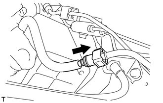
Line up the pipe and connector and push them together until a "click" sound is heard.
- NOTICE:
- ·
Check that there are no scratches or foreign objects on the connecting part.
·If the pipe is difficult to push into the connector, apply a small amount of clean engine oil to the tip of the pipe and reinsert it.
·After connecting, check that the pipe and connector are securely connected by pulling on them.
23841B
34.INSTALL EFI FUEL PIPE CLAMP
Install the EFI fuel pipe clamp.
Be sure to install the clamp until the click sound is heard.
35.CONNECT NO. 2 ENGINE WIRE
Install the No. 2 engine wire with the bolt.
- Torque:
- 8.4 N*m (85 kgf*cm, 74 in.*lbf)
Install the No. 2 engine wire with the bolt.
- Torque:
- 8.4 N*m (85 kgf*cm, 74 in.*lbf)
Position the engine wire as illustrated and install it with the nut.
- Torque:
- 8.8 N*m (90 kgf*cm, 78 in.*lbf)
Connect the starter assembly connector.
77740
36.INSTALL CHARCOAL CANISTER ASSEMBLY
82046D
37.INSTALL BODY GROUND WIRE
Install the body ground wire with the 2 bolts.
38.CONNECT ENGINE WIRE (for RHD)
Engage the 4 clamps.
Attach of the grommet.
Connect the 3 connectors and engage the clamp, and then connect the engine wire.
39.CONNECT ENGINE WIRE (for LHD)
- HINT:
-
Use the same procedures described for the RHD side.
11452
40.INSTALL OIL LEVEL DIPSTICK GUIDE
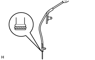
Apply a light coat of fresh engine oil to a new O-ring and install it onto the oil level dipstick guide.
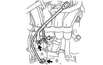
Install the oil level dipstick guide with the 2 bolts.
- Torque:
- Bolt A : 8.5 N*m (87 kgf*cm, 75 in.*lbf)
- Bolt B : 7.5 N*m (77 kgf*cm, 66 in.*lbf)
Install the wire harness clamp into the oil level gauge guide from the intake manifold side.
41.INSTALL GLOVE COMPARTMENT DOOR
55642
42.INSTALL NO. 2 INSTRUMENT PANEL UNDER COVER
43.INSTALL COOLER COMPRESSOR ASSEMBLY (for LHD)
44.INSTALL COOLER COMPRESSOR ASSEMBLY (for RHD)
32942
45.INSTALL NO. 1 OUTLET OIL COOLER HOSE (for Automatic Transmission)
32941
46.INSTALL NO. 1 INLET OIL COOLER HOSE (for Automatic Transmission)
16572
47.INSTALL OUTLET RADIATOR HOSE
16571
48.INSTALL INLET RADIATOR HOSE
27020
49.INSTALL GENERATOR ASSEMBLY
16361A
50.INSTALL FAN AND GENERATOR V BELT
44773F
51.CONNECT UNION TO CHECK VALVE HOSE
Connect the union to check valve hose.
78180P
52.CONNECT ACCELERATOR CONTROL CABLE ASSEMBLY
Install the accelerator control cable assembly with the 2 nuts.
Install the clamp.
17700
53.INSTALL AIR CLEANER ASSEMBLY
Install the air cleaner assembly with the 3 bolts.
- Torque:
- 7.5 N*m (77 kgf*cm, 66 in.*lbf)
Connect the vacuum hose to the vacuum sensor.
Connect the manifold absolute pressure sensor connector.
Install the intake air temperature sensor.
Install the No. 1 charcoal canister outlet hose and No. 2 charcoal canister outlet hose to the VSV.
Connect the VSV connector.
17881
54.INSTALL NO. 1 AIR CLEANER HOSE
Tighten the air cleaner hose clamp bolt and install the bolt.
- Torque:
- 7.5 N*m (77 kgf*cm, 66 in.*lbf)
55.ADD ENGINE COOLANT
56.ADD ENGINE OIL
57.ADD MANUAL TRANSMISSION OIL (for Manual Transmission)
58.ADD AUTOMATIC TRANSMISSION FLUID (for Automatic Transmission)
59.INSPECT FOR FUEL LEAK
60.INSPECT FOR ENGINE COOLANT LEAK
61.INSPECT FOR OIL LEAK
62.INSPECT FOR EXHAUST GAS LEAK
51443
63.INSTALL REAR ENGINE UNDER COVER (for Full Cover Type)
Install the rear engine under cover with the 8 bolts.
51441
64.INSTALL NO. 1 ENGINE UNDER COVER (for Full Cover Type)
Install the No. 1 engine under cover with the 8 bolts.
51441D
65.INSTALL ENGINE UNDER COVER (for Half Cover Type)
Install the engine under cover with the 3 bolts and clip.
66.INSPECT IGNITION TIMING
67.INSPECT ENGINE IDLE SPEED