Home › Audio / Visual / Telematics › AUDIO / VIDEO › AUDIO AND VISUAL SYSTEM(for Radio Receiver Type) › 2011.11–2015.08
RM19Y0E _56 Audio / Visual / Telematics _003000 AUDIO / VIDEO _0015166 AUDIO AND VISUAL SYSTEM(for Radio Receiver Type) J

AUDIO / VIDEO  AUDIO AND VISUAL SYSTEM(for Radio Receiver Type)  Steering Pad Switch Circuit  


DESCRIPTION

This circuit sends an operation signal from the steering wheel sub-assembly (steering pad switch) to the stereo component tuner assembly.

If there is an open in the circuit, the stereo system cannot be operated using the steering wheel sub-assembly (steering pad switch).

If there is a short in the circuit, the resulting condition is the same as if a switch were continuously pressed. Therefore, the stereo component tuner assembly cannot be operated using the steering wheel sub-assembly (steering pad switch), and the stereo component tuner assembly itself cannot function.

WIRING DIAGRAM
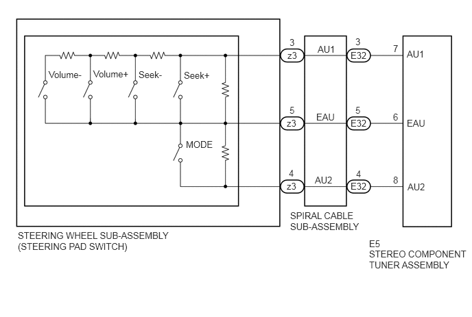
E232727E02
2.823,2.115 3.292,2.271 0.469,0.156 10 MODE 2.792,1.063 3.25,1.375 0.458,0.313 10 Seek+ 2.104,1.052 2.573,1.208 0.469,0.156 10 Seek- 1.417,1.042 2,1.198 0.583,0.156 10 Volume+ 0.74,1.052 1.292,1.208 0.552,0.156 10 Volume- 5.969,0.656 6.135,0.813 0.167,0.156 10 7 4.823,0.667 5.125,0.833 0.302,0.167 10 AU1 4.802,1.698 5.167,1.865 0.365,0.167 10 EAU 4.781,2.656 5.146,2.823 0.365,0.167 10 AU2 5.969,1.698 6.125,1.854 0.156,0.156 10 6 5.969,2.656 6.135,2.823 0.167,0.167 10 8 5.396,0.552 5.521,0.719 0.125,0.167 10 3 5.396,1.594 5.521,1.76 0.125,0.167 10 5 5.406,2.563 5.531,2.729 0.125,0.167 10 4 5.604,3.625 6.021,3.792 0.417,0.167 10 E5 5.323,0.76 5.74,0.927 0.417,0.167 10 E32 5.323,1.792 5.74,1.958 0.417,0.167 10 E32 5.323,2.75 5.74,2.917 0.417,0.167 10 E32 4.365,0.76 4.781,0.927 0.417,0.167 10 z3 4.354,1.792 4.771,1.958 0.417,0.167 10 z3 4.354,2.75 4.771,2.917 0.417,0.167 10 z3 4.396,0.563 4.573,0.729 0.177,0.167 10 3 4.396,1.594 4.521,1.76 0.125,0.167 10 5 4.385,2.552 4.51,2.719 0.125,0.167 10 4 6.177,0.74 6.531,0.896 0.354,0.156 10 AU1 6.177,1.792 6.563,1.948 0.385,0.156 10 EAU 6.188,2.76 6.573,2.917 0.385,0.156 10 AU2 5.604,3.781 7.104,4.438 1.5,0.656 10 STEREO COMPONENT TUNER ASSEMBLY 0.271,3.5 2.667,4.156 2.396,0.656 10 STEERING WHEEL SUB-ASSEMBLY (STEERING PAD SWITCH) 4.406,3.198 5.542,3.615 1.135,0.417 10 SPIRAL CABLE SUB-ASSEMBLY

PROCEDURE

1.INSPECT STEREO COMPONENT TUNER ASSEMBLY
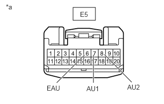
a.
E232953C02
1.531,0.156 2,0.427 0.469,0.271 1.958,1.156 1.958,1.74 true 1.771,1.156 1.188,1.74 true 2.188,1.146 2.76,1.729 true 0.125,0.063 0.552,0.302 0.427,0.24 10 *a 1.677,0.219 1.969,0.375 0.292,0.156 10 E5 0.979,1.771 1.354,1.958 0.375,0.188 10 EAU 1.813,1.781 2.188,1.969 0.375,0.188 10 AU1 2.667,1.75 3.042,1.938 0.375,0.188 10 AU2
*a Front view of wire harness connector
(to Stereo Component Tuner Assembly)


Remove the stereo component tuner assembly.

Click hereAudio / Visual / Telematics>AUDIO / VIDEO>RADIO RECEIVER>REMOVAL


b.

Measure the resistance according to the value(s) in the table below.

Standard Resistance:
Tester Connection Switch Condition Specified Condition
E5-7 (AU1) - E5-6 (EAU) No switch pushed 95 to 105 kΩ
E5-7 (AU1) - E5-6 (EAU) Seek+ switch pushed Below 2.5 Ω
E5-7 (AU1) - E5-6 (EAU) Seek- switch pushed 324 to 334 Ω
E5-7 (AU1) - E5-6 (EAU) Volume+ switch pushed 950 to 1050 Ω
E5-7 (AU1) - E5-6 (EAU) No switch pushed 2955 to 3265 Ω
E5-8 (SW2) - E5-6 (EAU) No switch pushed 95 to 105 kΩ
E5-8 (SW2) - E5-6 (EAU) MODE switch pushed Below 2.5 Ω


Result:
Proceed to
OK
NG


OK

NG

2.INSPECT STEERING WHEEL ASSEMBLY (STEERING PAD SWITCH)
a.

Remove the steering wheel sub-assembly.

Click hereSteering>STEERING COLUMN>STEERING WHEEL>REMOVAL


b.

Inspect the steering wheel sub-assembly.

Click hereSteering>STEERING COLUMN>STEERING WHEEL>INSPECTION

Result:
Proceed to
OK
NG


OK

3.INSPECT SPIRAL CABLE SUB-ASSEMBLY

NG

REPLACE STEERING WHEEL SUB-ASSEMBLY

3.INSPECT SPIRAL CABLE SUB-ASSEMBLY
a.

Remove the spiral cable sub-assembly.

Click hereSteering>STEERING COLUMN>STEERING COLUMN ASSEMBLY>DISASSEMBLY


b.

Inspect the steering wheel sub-assembly.

Click hereSteering>STEERING COLUMN>STEERING WHEEL>INSPECTION

Result:
Proceed to
OK
NG


OK

REPAIR OR REPLACE HARNESS OR CONNECTOR (STEREO COMPONENT TUNER - SPIRAL CABLE)

NG

REPLACE SPIRAL CABLE SUB-ASSEMBLY