1NR-VE COOLING COOLING FAN SYSTEM Cooling Fan Circuit
TECHNICAL DESCRIPTION
To control the cooling fan, the ECM turns on and off the cooling fan relay based on the engine coolant temperature, air conditioning switch, refrigerant pressure, engine speed and vehicle speed signals.
On vehicles equipped with a cooling fan resistor, the ECM turns the RAD/FAN No. 2 relay on and off to control the cooling fan speed in 2 stages.
WIRING DIAGRAM
Refer to System Diagram.
Click hereEngine / Hybrid System>1NR-VE COOLING>COOLING FAN SYSTEM>SYSTEM DIAGRAM
CAUTION / NOTICE / HINT
- NOTICE:
-
Inspect the fuses for circuits related to this system before performing the following procedure.
PROCEDURE
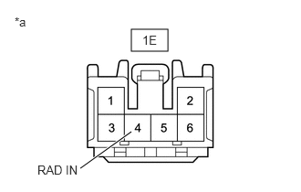
| *a | Front view of wire harness connector
(to No. 1 Integration Relay) |
Disconnect the 1E No. 1 integration relay connector.
Measure the voltage according to the value(s) in the table below.
- Standard Voltage:
Tester Connection Condition Specified Condition 1E-4(RAD IN) - Body ground Always 11 to 14 V
Connect the 1E No. 1 integration relay connector.
- Result:
Proceed to OK NG
OK
NG
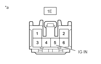
| *a | Front view of wire harness connector
(to No. 1 Integration Relay) |
Disconnect the 1E No. 1 integration relay connector.
Measure the voltage according to the value(s) in the table below.
- Standard Voltage:
Tester Connection Condition Specified Condition 1E-5(IG IN) - Body ground Always 11 to 14 V
Connect the 1E No. 1 integration relay connector.
- Result:
Proceed to OK NG
OK
NG
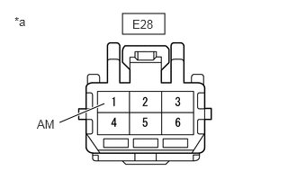
| *a | Front view of wire harness connector
(to Ignition or Starter Switch Assembly) |
Disconnect the E28 ignition or starter switch assembly connector.
Measure the voltage according to the value(s) in the table below.
- Standard Voltage:
Tester Connection Condition Specified Condition E28-1(AM) - Body ground Always 11 to 14 V
Connect the E28 ignition or starter switch assembly connector.
- Result:
Proceed to OK NG
OK
NG
Inspect the ignition or starter switch assembly.
Click hereEngine / Hybrid System>1NR-VE STARTING>IGNITION SWITCH>INSPECTION
- Result:
Proceed to OK NG
OK
NG
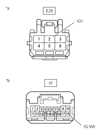
| *a | Front view of wire harness connector
(to Ignition or Starter Switch Assembly) |
| *b | Front view of wire harness connector
(to No. 1 Integration Relay) |
Disconnect the E28 ignition or starter switch assembly connector.
Disconnect the 1F No. 1 integration relay connector.
Measure the resistance according to the value(s) in the table below.
- Standard Resistance (Check for Open):
Tester Connection Condition Specified Condition E28-2(IG1) - 1F-18(IG SW) Always Below 1 Ω
- Standard Resistance (Check for Short):
Tester Connection Condition Specified Condition E28-2(IG1) or 1F-18(IG SW) - Body ground Always 10 kΩ or higher
Connect the 1F No. 1 integration relay connector.
Connect the E28 ignition or starter switch assembly connector.
- Result:
Proceed to OK NG
OK
NG
Disconnect the 1E and 1F No. 1 integration relay connectors.
Inspect the IG2 relay.
Click hereEngine / Hybrid System>1NR-VE ENGINE CONTROL>INTEGRATION RELAY>INSPECTION
Inspect the RAD/FAN No. 1 relay.
Click hereEngine / Hybrid System>1NR-VE ENGINE CONTROL>INTEGRATION RELAY>INSPECTION
w/ cooling fan resistor
Inspect the RAD/FAN No. 2 relay.
Click hereEngine / Hybrid System>1NR-VE ENGINE CONTROL>INTEGRATION RELAY>INSPECTION
Connect the 1E and 1F No. 1 integration relay connectors.
- Result:
Proceed to OK NG
OK
NG
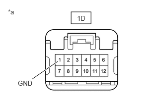
| *a | Front view of wire harness connector
(to No. 1 Integration Relay) |
Disconnect the 1D No. 1 integration relay connector.
Measure the resistance according to the value(s) in the table below.
- Standard Resistance (Check for Open):
Tester Connection Condition Specified Condition 1D-1(GND) - Body ground Always Below 1 Ω
Connect the 1D No. 1 integration relay connector.
- Result:
Proceed to OK NG
OK
NG
Confirm the vehicle type.
- Result:
Result Proceed to w/o cooling fan resistor A w/ cooling fan resistor B
A
B
Inspect the cooling fan resistor.
Click hereEngine / Hybrid System>1NR-VE COOLING>COOLING FAN RESISTOR>ON-VEHICLE INSPECTION
- Result:
Proceed to OK NG
OK
NG
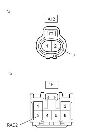
| *a | Front view of wire harness connector
(to Cooling Fan Resistor) |
| *b | Front view of wire harness connector
(to Integration Relay) |
Disconnect the A12 cooling fan resistor connector.
Disconnect the 1E No. 1 integration relay connector.
Measure the resistance according to the value(s) in the table below.
- Standard Resistance (Check for Open):
Tester Connection Condition Specified Condition A12-2(+) - 1E-3(RAD2) Always Below 1 Ω
- Standard Resistance (Check for Short):
Tester Connection Condition Specified Condition A12-2(+) or 1E-3(RAD2) - Body ground Always 10 kΩ or higher
Connect the 1E No. 1 integration relay connector.
Connect the A12 cooling fan resistor connector.
- Result:
Proceed to OK NG
OK
NG
Inspect the cooling fan motor.
Click hereEngine / Hybrid System>1NR-VE COOLING>COOLING FAN MOTOR>ON-VEHICLE INSPECTION
- Result:
Proceed to OK NG
OK
NG
Confirm the vehicle type.
- Result:
Result Proceed to w/o cooling fan resistor A w/ cooling fan resistor B
A
B
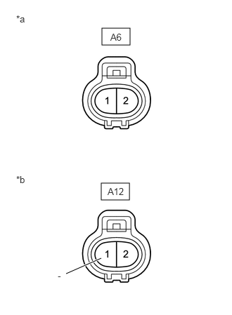
| *a | Front view of wire harness connector
(to Cooling Fan Motor) |
| *b | Front view of wire harness connector
(to Cooling Fan Resistor) |
Disconnect the A6 cooling fan motor connector.
Disconnect the A12 cooling fan resistor connector.
Measure the resistance according to the value(s) in the table below.
- Standard Resistance (Check for Open):
Tester Connection Condition Specified Condition A6-2 - A12-1(-) Always Below 1 Ω
- Standard Resistance (Check for Short):
Tester Connection Condition Specified Condition A6-2 or A12-1(-) - Body ground Always 10 kΩ or higher
Connect the A12 cooling fan resistor connector.
Connect the A6 cooling fan motor connector.
- Result:
Proceed to OK NG
OK
NG
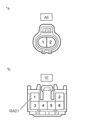
| *a | Front view of wire harness connector
(to Cooling Fan Motor) |
| *b | Front view of wire harness connector
(to No. 1 Integration Relay) |
Disconnect the A6 cooling fan motor connector.
Disconnect the 1E No. 1 integration relay connector.
Measure the resistance according to the value(s) in the table below.
- Standard Resistance (Check for Open):
Tester Connection Condition Specified Condition A6-2 - 1E-1(RAD1) Always Below 1 Ω
- Standard Resistance (Check for Short):
Tester Connection Condition Specified Condition A6-2 or 1E-1(RAD1) - Body ground Always 10 kΩ or higher
Connect the A6 cooling fan motor connector.
Connect the 1E No. 1 integration relay connector.
- Result:
Proceed to OK NG
OK
NG
Disconnect the A6 cooling fan motor connector.
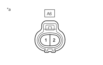
| *a | Front view of wire harness connector
(to Cooling Fan Motor) |
Measure the resistance according to the value(s) in the table below.
- Standard Resistance:
Tester Connection Condition Specified Condition A6-1 - Body ground Always Below 1 Ω
Connect the A6 cooling fan motor connector.
- Result:
Proceed to OK NG
OK
NG
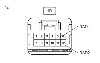
| *a | Front view of wire harness connector
(to No. 1 Integration Relay) |
Disconnect the 1D No. 1 Integration relay connector.
Disconnect the A24 ECM connector.
Measure the resistance according to the value(s) in the table below.
- Standard Resistance (Check for Open):
Tester Connection Condition Specified Condition 1D-6(RAD1-) - A24-9(FAN1) Always Below 1 Ω
- Standard Resistance (Check for Short):
Tester Connection Condition Specified Condition 1D-6(RAD1-) or A24-9(FAN1) - Body ground Always 10 kΩ or higher
w/ cooling fan resistor
Measure the resistance according to the value(s) in the table below.
- Standard Resistance (Check for Open):
Tester Connection Condition Specified Condition 1D-12(RAD2-) - A24-10(FAN2) Always Below 1 Ω
- Standard Resistance (Check for Short):
Tester Connection Condition Specified Condition 1D-12(RAD2-) or A24-10(FAN2) - Body ground Always 10 kΩ or higher
Connect the A24 ECM connector.
Connect the 1D No. 1 Integration relay connector.
- Result:
Proceed to OK NG
OK
NG
Disconnect the C50 ECM connector.
Measure the resistance according to the value(s) in the table below.
- Standard Resistance:
Tester Connection Condition Specified Condition C50-4(E01) - Body ground Always Below 1 Ω
Connect the C50 ECM connector.
- Result:
Proceed to OK NG
OK
NG