Home › Vehicle Interior › DOOR LOCK › WIRELESS DOOR LOCK CONTROL SYSTEM › from 2015.08
RM19Y0E _58 Vehicle Interior _003005 DOOR LOCK _0015187 WIRELESS DOOR LOCK CONTROL SYSTEM J

DOOR LOCK  WIRELESS DOOR LOCK CONTROL SYSTEM  No Answer-back  


DESCRIPTION

In some cases, wireless door lock control functions are normal but the hazard warning lights and security buzzer* do not answer-back. In such a case, the hazard warning light signal and security buzzer signal* output from the main body ECU (fuse block assembly) may be malfunctioning.

*: w/ Theft Warning ECU Assembly


HINT:

The security buzzer is built into the theft warning ECU assembly.


WIRING DIAGRAM
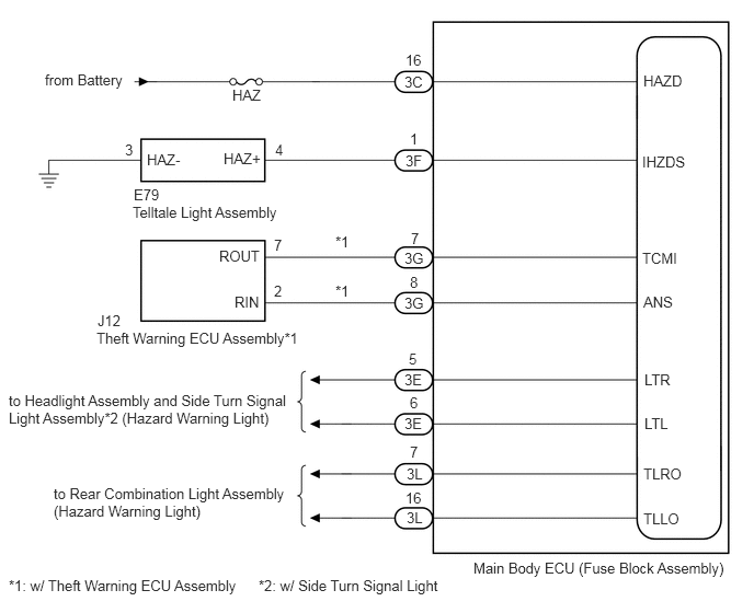
B419119E01
0.427,0.677 1.635,1.083 1.208,0.406 10 false from Battery 1.26,1.938 3.094,2.385 1.833,0.448 10 false Telltale Light Assembly 0.917,3.135 3.719,3.531 2.802,0.396 10 false Theft Warning ECU Assembly*1 4.5,5.323 7.104,5.719 2.604,0.396 10 false Main Body ECU (Fuse Block Assembly) 0.083,3.729 2.781,4.625 2.698,0.896 10 false to Headlight Assembly and Side Turn Signal Light Assembly*2 (Hazard Warning Light) 0.51,4.615 2.781,5.5 2.271,0.885 10 false to Rear Combination Light Assembly (Hazard Warning Light) 0.083,5.49 2.667,5.823 2.583,0.333 10 false *1: w/ Theft Warning ECU Assembly 2.458,5.49 5.042,5.823 2.583,0.333 10 false *2: w/ Side Turn Signal Light 3.188,2.219 3.677,2.573 0.49,0.354 10 false *1 0.927,2.969 1.417,3.323 0.49,0.354 10 false J12 1.271,1.771 1.76,2.125 0.49,0.354 10 false E79 2.083,2.354 2.771,2.698 0.688,0.344 10 false ROUT 2.229,2.792 2.917,3.135 0.688,0.344 10 false RIN 2.604,2.25 3.094,2.604 0.49,0.354 10 false 7 2.604,2.688 3.094,3.042 0.49,0.354 10 false 2 3.906,2.188 4.396,2.542 0.49,0.354 10 false 7 3.188,2.688 3.677,3.042 0.49,0.354 10 false *1 3.896,2.604 4.385,2.958 0.49,0.354 10 false 8 3.844,0.698 4.333,1.052 0.49,0.354 10 false 3C 3.854,1.448 4.344,1.802 0.49,0.354 10 false 3F 3.844,2.375 4.333,2.729 0.49,0.354 10 false 3G 3.844,2.802 4.333,3.156 0.49,0.354 10 false 3G 3.844,3.531 4.333,3.885 0.49,0.354 10 false 3E 3.844,3.948 4.333,4.302 0.49,0.354 10 false 3E 3.865,4.427 4.354,4.781 0.49,0.354 10 false 3L 3.865,4.844 4.354,5.198 0.49,0.354 10 false 3L 3.854,0.49 4.344,0.844 0.49,0.354 10 false 16 3.896,1.24 4.385,1.594 0.49,0.354 10 false 1 3.885,3.333 4.375,3.688 0.49,0.354 10 false 5 3.896,3.75 4.385,4.104 0.49,0.354 10 false 6 3.896,4.219 4.385,4.573 0.49,0.354 10 false 7 3.854,4.656 4.344,5.01 0.49,0.354 10 false 16 2.208,0.823 2.698,1.177 0.49,0.354 10 false HAZ 2.125,1.427 2.708,1.792 0.583,0.365 10 false HAZ+ 1.396,1.438 1.979,1.802 0.583,0.365 10 false HAZ- 2.615,1.344 3.104,1.698 0.49,0.354 10 false 4 1.188,1.344 1.677,1.698 0.49,0.354 10 false 3 6.104,1.458 6.719,1.802 0.615,0.344 10 false IHZDS 6.115,0.688 6.698,1.042 0.583,0.354 10 false HAZD 6.104,2.375 6.719,2.719 0.615,0.344 10 false TCMI 6.115,2.792 6.729,3.135 0.615,0.344 10 false ANS 6.125,3.531 6.74,3.875 0.615,0.344 10 false LTR 6.125,3.948 6.74,4.292 0.615,0.344 10 false LTL 6.115,4.427 6.729,4.771 0.615,0.344 10 false TLRO 6.115,4.854 6.729,5.198 0.615,0.344 10 false TLLO

CAUTION / NOTICE / HINT

NOTICE:

Perform this inspection with the customize parameters at the initial settings.

Click hereVehicle Interior>DOOR LOCK>WIRELESS DOOR LOCK CONTROL SYSTEM>CUSTOMIZE PARAMETERS


PROCEDURE

1.CHECK WIRELESS ANSWER-BACK OPERATION
a.

Check the wireless answer-back operation by wireless door lock control function.

Result:
Result Proceed to
Only hazard warning light answer-back does not occur. A
Only security buzzer answer-back does not occur.* B


*: w/ Theft Warning ECU Assembly


A

2.CHECK HAZARD WARNING LIGHTS

B

3.CHECK HARNESS AND CONNECTOR (MAIN BODY ECU (FUSE BLOCK ASSEMBLY) - THEFT WARNING ECU ASSEMBLY)
2.CHECK HAZARD WARNING LIGHTS
a.

Check that the hazard warning lights flash continuously when the telltale light assembly (hazard warning signal switch) is pressed.

OK:

Hazard warning lights flash continuously.


Result:
Result Proceed to
OK (for LHD) A
OK (for RHD) B
NG C


A

REPLACE MAIN BODY ECU (FUSE BLOCK ASSEMBLY)

B

REPLACE MAIN BODY ECU (FUSE BLOCK ASSEMBLY)

C

3.CHECK HARNESS AND CONNECTOR (MAIN BODY ECU (FUSE BLOCK ASSEMBLY) - THEFT WARNING ECU ASSEMBLY)
a.

Disconnect the 3G main body ECU (fuse block assembly) connector.


b.

Disconnect the J12 theft warning ECU assembly connector.


c.

Measure the resistance according to the value(s) in the table below.

Standard Resistance (Check for Open):
Tester Connection Condition Specified Condition
3G-7 - J12-7 (ROUT) Always Below 1 Ω
3G-8 - J12-2 (RIN) Always Below 1 Ω


Standard Resistance (Check for Short):
Tester Connection Condition Specified Condition
3G-7 or J12-7 (ROUT) - Body ground Always 10 kΩ or higher
3G-8 or J12-2 (RIN) - Body ground Always 10 kΩ or higher


Result:
Proceed to
OK
NG


OK

NG

REPAIR OR REPLACE HARNESS OR CONNECTOR