2ZR-FXE EMISSION CONTROL EGR VALVE INSTALLATION
PROCEDURE

 25620
1.INSTALL EGR VALVE ASSEMBLY
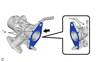
| *a | Claw |
Install a new EGR valve gasket to the EGR valve assembly.
- NOTICE:
-
Make sure that the claws of the EGR valve gasket are toward the EGR valve assembly side.
Set the EGR valve assembly to the EGR pipe with cooler sub-assembly.
Using an E8 "TORX" socket wrench, install the stud bolt to the camshaft housing sub-assembly.
- Torque:
- 9.5 N*m (97 kgf*cm, 84 in.*lbf)
- HINT:
-
If a stud bolt is deformed or the threads are damaged, replace it.
Install the EGR valve assembly to the EGR pipe with cooler sub-assembly with the 3 nuts.
- Torque:
- 21 N*m (214 kgf*cm, 15 ft.*lbf)
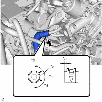
| *a | 0 to 4 mm (0 to 0.157 in.) |
| *b | Top of Vehicle |
| *c | Left Side of Vehicle |
| *d | 180° |
| *e | Paint Mark |
Connect the water by-pass hose to the EGR valve assembly and slide the clip to secure it.
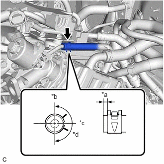
| *a | 0 to 4 mm (0 to 0.157 in.) |
| *b | Top of Vehicle |
| *c | Left Side of Vehicle |
| *d | 180° |
Connect the No. 6 water by-pass hose to the EGR valve assembly and slide the clip to secure it.
Connect the EGR valve assembly connector.
25610
2.INSTALL EGR PIPE ASSEMBLY
G9200
3.INSTALL INVERTER WITH CONVERTER ASSEMBLY
- CAUTION:
-
Wear insulated gloves.
- NOTICE:
- ·
Be careful not to damage the surrounding components when installing the inverter with converter assembly.
·To prevent damage to the inverter with converter assembly, do not hold the coolant pipe, bracket or connector when securing the inverter with converter assembly.
·To prevent damage due to static electricity, do not touch the terminals of the inverter with converter assembly connector.
·Make sure to seal the inverter with converter assembly with the connector cover assembly or tape (non-residue type) etc., until just before installing the inverter with converter assembly to prevent entry of foreign matter and water.
Remove the rope or equivalent that was securing the inverter with converter assembly.
Temporarily install the inverter with converter assembly with the 5 bolts and 2 nuts.
- NOTICE:
-
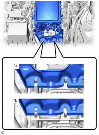 0.479,2.198 0.667,2.396 0.188,0.198 10 true *a 0.469,3.396 0.646,3.573 0.177,0.177 10 true *b
*a Correct *b Incorrect
-
Make sure that the inverter with converter assembly is positioned so that the stud bolts are in contact with the base of the U-shaped portions of the No. 1 inverter bracket.
Fully tighten the bolt (A).
- Torque:
- 25 N*m (255 kgf*cm, 18 ft.*lbf)
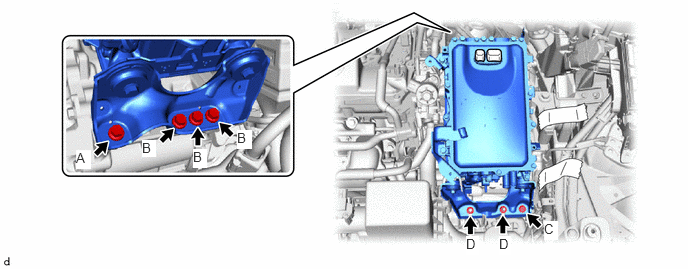
Fully tighten the 3 bolts (B).
- Torque:
- 25 N*m (255 kgf*cm, 18 ft.*lbf)
Fully tighten the bolt (C).
- Torque:
- 25 N*m (255 kgf*cm, 18 ft.*lbf)
Fully tighten the 2 nuts (D).
- Torque:
- 25 N*m (255 kgf*cm, 18 ft.*lbf)
821H2
4.CONNECT HV AIR CONDITIONING WIRE
821H1
5.CONNECT HV FLOOR UNDER WIRE
82121
6.CONNECT ENGINE WIRE
33820B
7.CONNECT TRANSMISSION CONTROL CABLE ASSEMBLY
74404A
8.INSTALL BATTERY CLAMP SUB-ASSEMBLY
89661
9.INSTALL ECM
G3834
10.INSTALL SERVICE PLUG GRIP
11.INSTALL AUXILIARY BATTERY
82121
12.CONNECT ENGINE WIRE
55701J
13.INSTALL OUTER COWL TOP PANEL SUB-ASSEMBLY (for LHD)
55701J
14.INSTALL OUTER COWL TOP PANEL SUB-ASSEMBLY (for RHD)
55736D
15.INSTALL COWL BODY MOUNTING REINFORCEMENT LH
55735C
16.INSTALL COWL BODY MOUNTING REINFORCEMENT RH
55735A
17.INSTALL WATER GUARD PLATE LH (for TMC Made RHD)
55737B
18.INSTALL NO. 1 HEATER AIR DUCT SPLASH SHIELD SEAL
19.INSTALL WINDSHIELD WIPER MOTOR AND LINK ASSEMBLY
20.ADD ENGINE COOLANT (for Engine)
21.INSPECT FOR COOLANT LEAK (for Engine)
51441
22.INSTALL NO. 1 ENGINE UNDER COVER