BRAKE SYSTEM (OTHER) BRAKE BOOSTER(for LHD) REMOVAL
CAUTION / NOTICE / HINT
The necessary procedures (adjustment, calibration, initialization, or registration) that must be performed after parts are removed, installed, or replaced during brake booster with master cylinder assembly removal/installation are shown below.
| Replaced Part or Performed Procedure | Necessary Procedure | Effect/Inoperative Function when Necessary Procedure not Performed | Link |
|---|---|---|---|
|
*1: When performing learning using the GTS. Click here( |
|||
| Auxiliary battery terminal is disconnected/reconnected | Perform steering sensor zero point calibration | Lane departure alert system (w/ Steering Control) | ( ) |
| Toyota parking assist-sensor system*1 | |||
| Parking support brake system*1 | |||
| Simple intelligent parking assist system*1 | |||
| Pre-collision system | |||
| Memorize steering angle neutral point | Panoramic view monitor system | ()
|
|
| Initialize back door lock | Power door lock control system | ()
|
|
| Replacement of brake booster with master cylinder assembly | 1.
Bleed air 2.
Clear the data stored during previous linear solenoid valve offset learning, ABS holding solenoid valve learning, brake pedal stroke sensor assembly zero point calibration and system information memorization. 3.
Perform linear solenoid valve offset learning, ABS holding solenoid valve learning, brake pedal stroke sensor assembly zero point calibration and system information memorization. |
·
DTCs are stored ·
ABS warning light illuminates ·
Brake warning light / yellow (minor malfunction) illuminates ·
Slip indicator light illuminates ·
VSC disabled or malfunctions |
for Initialization:()
for Calibration:( )
|
1.
Clear zero point calibration data. 2.
Perform yaw rate and acceleration sensor zero point calibration. |
|||
- NOTICE:
-
While the auxiliary battery is connected, even if the power switch is off, the brake control system activates when the brake pedal is depressed or any door courtesy switch turns on. Therefore, when servicing the brake system components, do not operate the brake pedal or open/close the doors while the auxiliary battery is connected.
PROCEDURE

 1. PRECAUTION
- NOTICE:
-
After turning the power switch off, waiting time may be required before disconnecting the cable from the negative (-) auxiliary battery terminal. Therefore, make sure to read the disconnecting the cable from the negative (-) auxiliary battery terminal notices before proceeding with work.
-
Click hereGeneral>INTRODUCTION>REPAIR INSTRUCTION>PRECAUTION
2.REMOVE WINDSHIELD WIPER MOTOR AND LINK ASSEMBLY
55737B
3.REMOVE NO. 1 HEATER AIR DUCT SPLASH SHIELD SEAL
55736D
4.REMOVE COWL BODY MOUNTING REINFORCEMENT LH
55735C
5.REMOVE COWL BODY MOUNTING REINFORCEMENT RH
55701J
6.REMOVE OUTER COWL TOP PANEL SUB-ASSEMBLY
51410
7.REMOVE NO. 1 ENGINE UNDER COVER ASSEMBLY (for M20A-FXS)
8.PERFORM ACCUMULATOR PRESSURE ZERO DOWN
Using the GTS, perform the accumulator pressure zero down.
Connect the GTS to the DLC3 with the power switch off.
Turn the power switch on (IG).
Turn the GTS on and enter the following menus: Chassis / ABS/VSC/TRC / Utility / ECB (Electronically Controlled Brake system) Utility.
- Chassis > ABS/VSC/TRC > Utility
-
Tester Display ECB Utility - 50005 105 167
Select "Motor Invalid" on the "ECB (Electronically Controlled Brake system) Utility" screen.
Perform "Motor Invalid" according to the display on the GTS.
Enter the following menus: Chassis / ABS/VSC/TRC / Utility / ECB (Electronically Controlled Brake system) Utility.
- Chassis > ABS/VSC/TRC > Utility
-
Tester Display ECB Utility - 50005 105 167
Select "ECB (Electronically Controlled Brake system) Invalid" on the "ECB (Electronically Controlled Brake system) Utility" screen.
Perform "ECB (Electronically Controlled Brake system) Invalid" according to the display on the GTS
Depress the brake pedal 40 times or more to return all the fluid in the accumulator back to the reservoir.
- HINT:
-
A buzzer may sound due to low accumulator pressure. As this is not a malfunction, continue the procedure.
Check that the brake pedal is firm.
- NOTICE:
-
If the brake pedal is not firm or the pump motor continues to operate even after depressing the brake pedal 40 times or more, the accumulator pressure zero down is not complete.
Turn the GTS off and turn the power switch off.
Disconnect the GTS from the DLC3.
Disconnect the cable from the negative (-) auxiliary battery terminal.
for M20A-FXS:
Click hereGeneral>MAINTENANCE>M20A-FXS AUXILIARY BATTERY>REMOVAL
for 2ZR-FXE:
Click hereGeneral>MAINTENANCE>2ZR-FXE AUXILIARY BATTERY>REMOVAL
When the accumulator pressure zero down could not be performed using the GTS.
- NOTICE:
-
If DTCs are output, accumulator pressure zero down may not be complete. In this case, perform the following procedure.
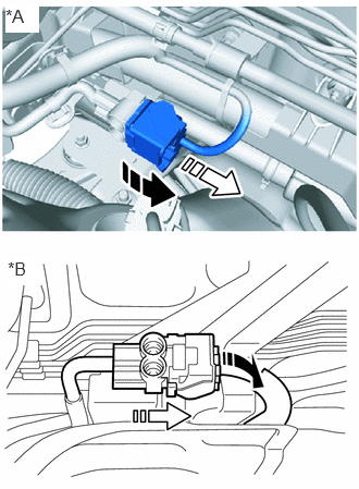
| *A | for 2ZR-FXE |
| *B | for M20A-FXS |

|
Release the lock lever |

|
Disconnect the connector |
With the power switch off, release the lock lever and disconnect the brake booster pump assembly connector as shown in the illustration.
Depress the brake pedal 40 times or more to return all the fluid in the accumulator back to the reservoir.
Check that the brake pedal is firm.
- NOTICE:
-
If the brake pedal is not firm or the pump motor continues to operate even after depressing the brake pedal 40 times or more, the accumulator pressure zero down is not complete.
Disconnect the cable from the negative (-) auxiliary battery terminal.
for M20A-FXS:
Click hereGeneral>MAINTENANCE>M20A-FXS AUXILIARY BATTERY>REMOVAL
for 2ZR-FXE:
Click hereGeneral>MAINTENANCE>2ZR-FXE AUXILIARY BATTERY>REMOVAL
9.DRAIN BRAKE FLUID
- NOTICE:
-
If brake fluid leaks onto any painted surface, immediately wash it off.
55225
10.REMOVE DASH PANEL HEAT INSULATOR (for M20A-FXS)
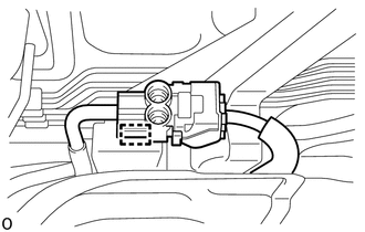
Disengage the clamp to separate the brake booster pump assembly wire harness and engine room main wire from the dash panel heat insulator.
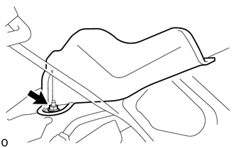
Remove the nut.
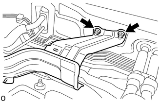
Remove the 2 nuts and dash panel heat insulator.
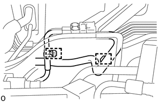
Disengage the 2 clamps to separate the brake booster pump assembly wire harness and engine room main wire from the dash panel heat insulator.
82111
11.DISCONNECT ENGINE ROOM MAIN WIRE
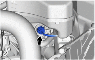
Disconnect the connector from the brake booster with master cylinder assembly.
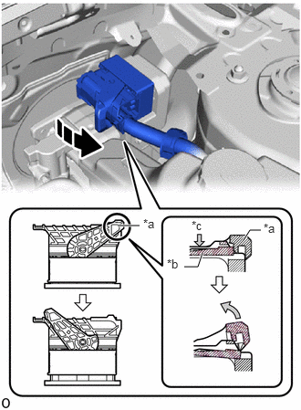
| *a | Lock Lever |
| *b | Lock Arm |
| *c | Push |
|
|
Release the lock lever |
Push the lock arm of the connector to release the lock and rotate the lock lever to the position shown in the illustration.
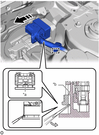
| *a | Screwdriver Insertion Point |
| *b | Pre-lock |
|
|
Disconnect the connector |
Using a screwdriver, release the pre-lock and disconnect the connector from the brake booster with master cylinder assembly as shown in the illustration.
Disengage the clamp to separate the engine room main wire.
44572C
12.DISCONNECT NO. 2 BRAKE ACTUATOR HOSE
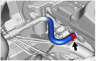
Slide the clip and disconnect the No. 2 brake actuator hose from the brake booster with master cylinder assembly.
44551C
13.SEPARATE NO. 1 BRAKE ACTUATOR TUBE
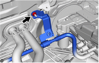
Remove the nut and separate the No. 1 brake actuator tube from the vehicle body.
14.SEPARATE BRAKE LINE
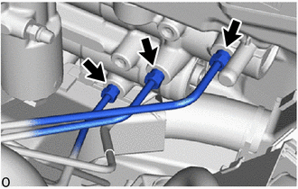
Using a union nut wrench, disconnect the 3 brake lines from the brake booster with master cylinder assembly.
- NOTICE:
- ·
Do not kink or damage the brake lines.
·Do not allow any foreign matter such as dirt or dust to enter the brake lines from the connecting parts.
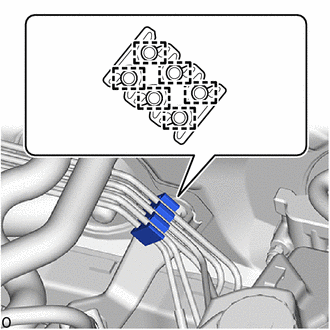
Disengage the 6 clamps to remove the No. 1 brake tube clamp from the brake lines.
- NOTICE:
-
Do not kink or damage the brake lines.
67914
15.REMOVE FRONT DOOR SCUFF PLATE LH
62112
16.REMOVE COWL SIDE TRIM BOARD LH
87211
17.REMOVE NO. 1 AIR DUCT
47101A
18.REMOVE BRAKE PEDAL RETURN SPRING
47264A
19.REMOVE PUSH ROD PIN
47210L
20.REMOVE BRAKE BOOSTER WITH MASTER CYLINDER ASSEMBLY
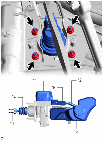
| *1 | Skid Control ECU |
| *2 | No. 1 Reservoir Hose |
| *3 | Brake Master Cylinder Push Rod Clevis |
| *4 | Boot |
| *5 | Master Cylinder Reservoir Assembly |
| *6 | Brake Actuator Bracket |
Remove the 4 nuts and brake booster with master cylinder assembly.
- NOTICE:
- ·
Do not kink or damage the brake lines.
·Do not carry the brake booster with master cylinder assembly by the parts shown in the illustration.
·Be careful not to allow any brake fluid to enter the connector.
44785C
21.REMOVE BRAKE BOOSTER GASKET
Remove the brake booser gasket from the brake booster with master cylinder assembly.