M20A-FXS HYBRID / BATTERY CONTROL BATTERY VOLTAGE SENSOR INSTALLATION
PROCEDURE

 89892A
1.INSTALL BATTERY VOLTAGE SENSOR
- CAUTION:
-
Be sure to wear insulated gloves and protective goggles.
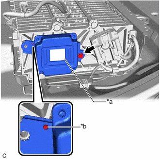
| *a | Bluish green Label |
| *b | Pin |
Install the battery voltage sensor to the HV battery with the bolt.
- Torque:
- 7.5 N*m (76 kgf*cm, 66 in.*lbf)
- NOTICE:
- ·
Check color of the label.
·If the battery voltage sensor has been struck or dropped, replace it.
·Make sure to align the hole of the battery voltage sensor with the pin.
Connect the battery voltage sensor connector.
- NOTICE:
-
Make sure that the connector is connected securely.
G92Q1
2.INSTALL NO. 1 HV BATTERY SHIELD PANEL
- CAUTION:
-
Be sure to wear insulated gloves and protective goggles.
Pull back the Rear hybrid battery shield sub-assembly to install the No. 1 HV battery shield panel to the HV battery.
- HINT:
-
Pull back the Rear hybrid battery shield sub-assembly until there is sufficient clearance for the 2 stud bolts of the No. 1 HV battery shield panel.
Install the bolt and 2 nuts.
- Torque:
- 7.5 N*m (76 kgf*cm, 66 in.*lbf)
Connect the battery voltage sensor connector.
Engage the clamp.
G920L
3.INSTALL UPPER NO. 1 HYBRID BATTERY COVER SUB-ASSEMBLY
- CAUTION:
-
Be sure to wear insulated gloves and protective goggles.
Install the upper No. 1 hybrid battery cover sub-assembly to the HV battery with the 7 bolts and 6 nuts.
- Torque:
- 7.5 N*m (76 kgf*cm, 66 in.*lbf)
Move the HV battery to the installation position.
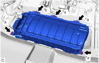
| *a | Bolt (A)
(Bolt Length: 25 mm (0.984 in.)) |
| *b | Bolt (B)
(Bolt Length: 24 mm (0.945 in.)) |
Install the 4 bolts (A) and bolt (B).
- Torque:
- 19 N*m (194 kgf*cm, 14 ft.*lbf)
- NOTICE:
- ·
Do not allow foreign matter, such as grease or oil, to adhere to the bolts of the HV battery.
·To prevent the wire harness from being caught, make sure to bundle the wire harness using insulating tape or equivalent.
·As bolts with 2 different lengths are used, make sure to install each bolt to the correct position.
·If the HV battery has been struck or dropped, replace it.
82161
4.CONNECT FLOOR WIRE
G92PC
5.INSTALL NO. 1 HV BATTERY PROTECTOR
82161
6.CONNECT FLOOR WIRE
821H1
7.CONNECT FLOOR UNDER WIRE
G92N4A
8.INSTALL NO. 1 HV BATTERY COVER PANEL RH
G9230
9.INSTALL BATTERY COOLING BLOWER ASSEMBLY
71033
10.INSTALL REAR SEAT CUSHION LEG SUB-ASSEMBLY
76971G
11.INSTALL REAR UNDER COVER
76974F
12.INSTALL REAR UNDER SIDE COVER LH
67918A
13.INSTALL REAR DOOR SCUFF PLATE LH
76973F
14.INSTALL REAR UNDER SIDE COVER RH
- HINT:
-
Use the same procedure as for the LH side.
67917A
15.INSTALL REAR DOOR SCUFF PLATE RH
- HINT:
-
Use the same procedure as for the LH side.
72693
16.INSTALL REAR SEAT CUSHION LOCK HOOK
17.INSTALL BENCH TYPE REAR SEAT CUSHION ASSEMBLY
73350C
18.CONNECT REAR CENTER SEAT OUTER BELT ASSEMBLY
G3834
19.INSTALL SERVICE PLUG GRIP
20.PERFORM INITIALIZATION