MIRROR (EXT) POWER MIRROR CONTROL SYSTEM TERMINALS OF ECU
CHECK MAIN BODY ECU (MULTIPLEX NETWORK BODY ECU) AND INSTRUMENT PANEL JUNCTION BLOCK ASSEMBLY (w/ Retract Mirror)
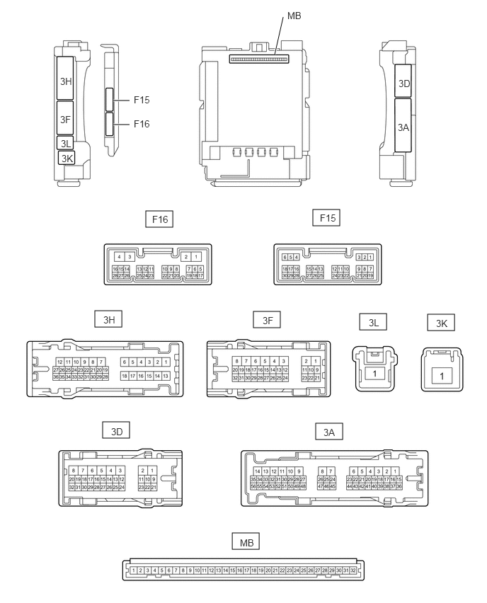
Remove the main body ECU (multiplex network body ECU) from the instrument panel junction block assembly.
for LHD:
Click herePower Source / Network>POWER DISTRIBUTION>MAIN BODY ECU (for LHD)>REMOVAL
for RHD:
Click herePower Source / Network>POWER DISTRIBUTION>MAIN BODY ECU (for RHD)>REMOVAL
Reconnect the instrument panel junction block assembly connectors.
Measure the resistance and voltage according to the value(s) in the table below.
- HINT:
-
Measure the values on the wire harness side with the connector disconnected.
| Terminal No. (Symbol) | Wiring Color | Terminal Description | Condition | Specified Condition |
|---|---|---|---|---|
| MB-11 (GND1) - Body ground | - | Ground | Always | Below 1 Ω |
| MB-31 (BECU) - Body ground | - | Battery power supply | Always | 11 to 14 V |
| MB-30 (ACC) - Body ground | - | Ignition power supply (ACC signal) | Ignition switch ACC | 11 to 14 V |
| MB-30 (ACC) - Body ground | - | Ignition power supply (ACC signal) | Ignition switch off | Below 1 V |
| MB-32 (IG) - Body ground | - | Ignition power supply (IG signal) | Ignition switch ON | 11 to 14 V |
| MB-32 (IG) - Body ground | - | Ignition power supply (IG signal) | Ignition switch off | Below 1 V |
Install the main body ECU (multiplex network body ECU) to instrument panel junction block assembly.
Measure the voltage according to the value(s) in the table below.
| Terminal No. (Symbol) | Wiring Color | Terminal Description | Condition | Specified Condition |
|---|---|---|---|---|
| F16-14 (RET) - Body ground | B - Body ground*1
G - Body ground*2 |
Power retract mirror motor drive voltage | Mirror retract switch on outer mirror switch assembly retracted position. | Below 1 V |
| Mirror retract switch on outer mirror switch assembly driving position. | 11 to 14 V | |||
| F16-15 (RTR) - Body ground | P - Body ground | Power retract mirror motor drive voltage | Mirror retract switch on outer mirror switch assembly auto retracted position. | Below 1 V |
| Mirror retract switch on outer mirror switch assembly driving position. | 11 to 14 V | |||
| F16-19 (RETR) - Body ground | L - Body ground | Power retract mirror motor drive voltage | Outer rear view mirror assembly moves to the retracted position. | Below 1 V |
| Outer rear view mirror assembly not move. | 11 to 14 V | |||
| F16-20 (RTRR) - Body ground | R - Body ground | Power retract mirror motor drive voltage | Outer rear view mirror assembly moves to the driving position. | Below 1 V |
| Outer rear view mirror assembly not move. | 11 to 14 V |
*1: for LHD
*2: for RHD
CHECK AIR CONDITIONING AMPLIFIER ASSEMBLY
Click hereVehicle Exterior>WINDOW / GLASS>WINDOW DEFOGGER SYSTEM>TERMINALS OF ECU
CHECK AIR CONDITIONING CONTROL ASSEMBLY
Click hereVehicle Exterior>WINDOW / GLASS>WINDOW DEFOGGER SYSTEM>TERMINALS OF ECU