3ZR-FAE ENGINE MECHANICAL ENGINE UNIT REMOVAL
CAUTION / NOTICE / HINT
The necessary procedures (adjustment, calibration, initialization, or registration) that must be performed after parts are removed, installed, or replaced during the engine assembly disassembly/reassembly are shown below.
| Replacement Part or Procedure | Necessary Procedure | Effect/Inoperative when not Performed | Link |
|---|---|---|---|
·
Replacement of camshaft timing gear assembly ·
Replacement of camshaft timing exhaust gear assembly |
Inspection After Repair | ·
Poor idle, etc. ·
Engine start function, etc. |
( ) |
PROCEDURE

 22210
1.REMOVE THROTTLE BODY ASSEMBLY
17111
2.REMOVE INTAKE MANIFOLD
17650
3.REMOVE PURGE VALVE (PURGE VSV)
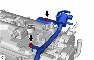
Remove the 2 bolts and purge valve (purge VSV) from the cylinder head cover sub-assembly.
23901
4.DISCONNECT FUEL TUBE SUB-ASSEMBLY
23807
5.REMOVE FUEL DELIVERY PIPE SUB-ASSEMBLY
23807V
6.REMOVE NO. 1 DELIVERY PIPE SPACER
23250
7.REMOVE FUEL INJECTOR ASSEMBLY
19500
8.REMOVE IGNITION COIL ASSEMBLY
11452
9.REMOVE ENGINE OIL LEVEL DIPSTICK GUIDE
Remove the engine oil level dipstick.
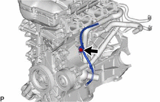
Remove the bolt and engine oil level dipstick guide.
Remove the O-ring from the engine oil level dipstick guide.
17167
10.REMOVE NO. 1 EXHAUST MANIFOLD HEAT INSULATOR
17118
11.REMOVE MANIFOLD STAY
17141
12.REMOVE EXHAUST MANIFOLD
43457
13.REMOVE DRIVE SHAFT BEARING BRACKET
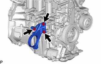
Remove the 3 bolts and drive shaft bearing bracket from the cylinder block sub-assembly.
12512C
14.REMOVE NO. 2 GENERATOR BRACKET
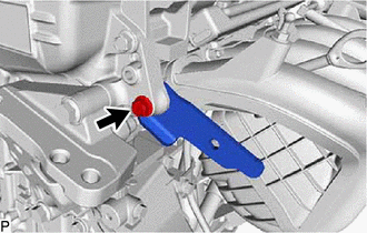
Remove the bolt and No. 2 generator bracket from the cylinder head sub-assembly.
16279
15.REMOVE NO. 3 WATER BY-PASS PIPE
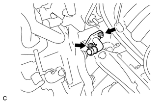
Remove the 2 nuts, No. 3 water by-pass pipe and gasket.
16268
16.DISCONNECT NO. 1 WATER BY-PASS PIPE
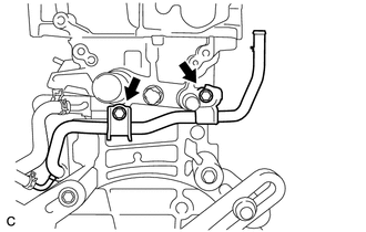
Remove the 2 bolts and No. 1 water by-pass pipe.
12261
17.REMOVE PCV HOSE
Remove the PCV hose from the PCV valve sub-assembly.
16267
18.DISCONNECT NO. 3 WATER BY-PASS HOSE
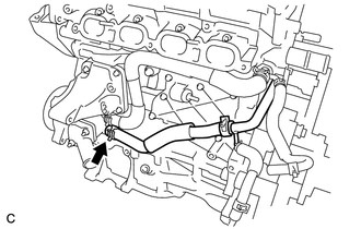
Slide the clip and disconnect the No. 3 water by-pass hose from the water inlet housing
16261
19.REMOVE WATER BY-PASS HOSE
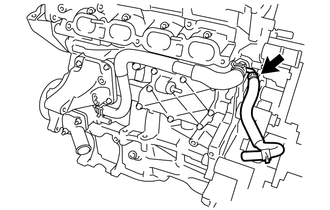
Slide the clip and remove the clamp and water by-pass hose.
16262
20.REMOVE WATER INLET HOSE
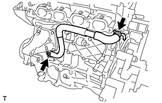
Slide the 2 clips and remove the water inlet hose.
16321
21.REMOVE WATER INLET
16331A
22.REMOVE THERMOSTAT
29300
23.REMOVE VACUUM PUMP ASSEMBLY
12551A
24.REMOVE NO. 1 VACUUM PUMP BRACKET
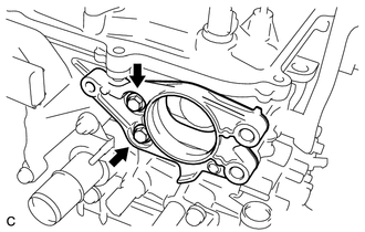
Remove the 2 bolts, No. 1 vacuum pump bracket and gasket.
25.REMOVE ENGINE OIL TEMPERATURE SENSOR
16620
26.REMOVE V-RIBBED BELT TENSIONER ASSEMBLY
Rotate the V-ribbed belt tensioner assembly clockwise and remove the 5 mm bi-hexagon wrench that was used to secure the V-ribbed belt tensioner assembly when removing the V-ribbed belt.
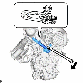
Rotate the V-ribbed belt tensioner assembly slightly clockwise and secure it using a 3 mm bi-hexagon wrench as shown in the illustration.
- HINT:
-
It is difficult to install the V-ribbed belt tensioner assembly when it is fully extended. When reusing the V-ribbed belt tensioner assembly, compress and secure the V-ribbed belt tensioner assembly before removing it.
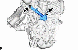
Remove the 2 bolts and V-ribbed belt tensioner assembly from the engine assembly.
27.REMOVE WIRE HARNESS CLAMP BRACKET
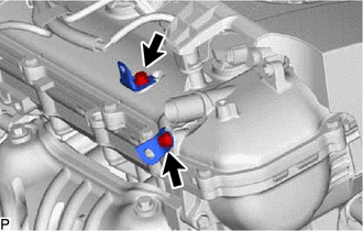
Remove the 2 bolts and 2 wire harness clamp brackets from the cylinder head cover sub-assembly.
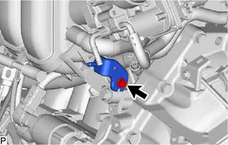
Remove the bolt and wire harness clamp bracket from the intake manifold.