INSTALLATION
Removal / installation · Vehicles built Jun 2006 – Sep 2006
Versions by build date: Jun 2006 – Sep 2006 Oct 2006 – May 2009 from Jun 2009
| 1. INSTALL ENGINE MOUNTING INSULATOR LH |

Install the engine mounting insulator LH with the 4 bolts.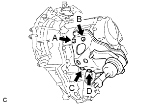

- Torque:
- 64 N*m{ 653 kgf*cm , 47 ft.*lbf }
- HINT:
- Tighten the bolts in order: A, B, C and D.
| 2. INSTALL ENGINE MOUNTING FRONT BRACKET |
Install the engine mounting front bracket with the 3 bolts.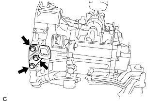
- Torque:
- 64 N*m{ 653 kgf*cm , 47 ft.*lbf }
| 3. INSTALL MANUAL TRANSMISSION CASE PROTECTOR |
Install the manual transmission case protector with the 2 bolts.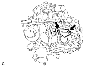
- Torque:
- 18 N*m{ 184 kgf*cm , 13 ft.*lbf }
| 4. INSTALL WIRE HARNESS CLAMP |
Install the 2 wire harness clamps with the 2 bolts.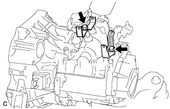
- Torque:
- 8.4 N*m{ 86 kgf*cm , 74 in.*lbf }
| 5. INSTALL CLUTCH LINE |
Install the clutch line and bracket with the 2 bolts.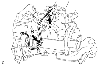
- Torque:
- Bolt A:
- 12 N*m{ 122 kgf*cm , 9 ft.*lbf }
- Bolt B:
- 7.0 N*m{ 71 kgf*cm , 62 in.*lbf }
| 6. INSTALL MANUAL TRANSAXLE ASSEMBLY |
Align the input shaft with the clutch disc and install the transaxle to the engine.
Install the 10 bolts.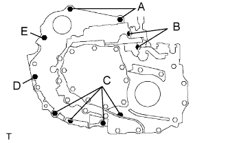
- Torque:
- Bolt A:
- 64 N*m{ 653 kgf*cm , 47 ft.*lbf }
- Bolt B:
- 46 N*m{ 470 kgf*cm , 34 ft.*lbf }
- Bolt C:
- 44 N*m{ 449 kgf*cm , 32 ft.*lbf }
- Bolt D:
- 46 N*m{ 470 kgf*cm , 34 ft.*lbf }
- Bolt E:
- 64 N*m{ 653 kgf*cm , 47 ft.*lbf }
- Bolt length:
- Bolt A:
- 60 mm (2.3622 in.)
- Bolt B:
- 60 mm (2.3622 in.)
- Bolt C:
- 32 mm (1.2598 in.)
- Bolt D:
- 65 mm (2.5591 in.)
- Bolt E:
- 74.5 mm (2.9331 in.)
| 7. CONNECT WIRE HARNESS |
Install the wire harness.
Connect the back-up light switch connector.
Install the ground cable with the bolt.
- Torque:
- 12 N*m{ 122 kgf*cm , 9 ft.*lbf }
| 8. INSTALL STARTER ASSEMBLY |
Install the starter assembly and clutch flexible hose bracket with the 3 bolts.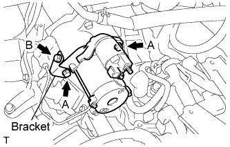
- Torque:
- Bolt A:
- 37 N*m{ 380 kgf*cm , 28 ft.*lbf }
- Bolt B:
- 12 N*m{ 120 kgf*cm , 9 ft.*lbf }
Connect the wire harness to terminal 30 and install the nut. Then, attach the terminal cap.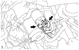
- Torque:
- 9.8 N*m{ 100 kgf*cm , 87 in.*lbf }
Connect the terminal 50 connector to the starter assembly.
| 9. INSTALL FRONT DRIVE SHAFT ASSEMBLY LH |
Coat the spline of the inboard joint shaft assembly with ATF.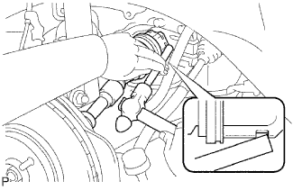
Align the shaft splines and install the drive shaft assembly LH with a brass bar and hammer.
- NOTICE:
- Set the shaft snap ring with the opening side facing down.
- Be careful not to damage the drive shaft dust cover, boot, and oil seal.
- Move the drive shaft assembly while keeping it level.
- Set the shaft snap ring with the opening side facing down.
| 10. INSTALL FRONT DRIVE SHAFT ASSEMBLY RH |
Coat the spline of the inboard joint shaft assembly with ATF.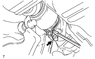
Install the front drive shaft the assembly RH.
Using a screwdriver, install a new bearing bracket hole snap ring.
- NOTICE:
- Do not damage the boot and oil seal.
- Move the drive shaft assembly while keeping it level.
- Do not damage the boot and oil seal.
Install a new bolt.
- Torque:
- 32 N*m{ 330 kgf*cm , 24 ft.*lbf }
| 11. INSTALL FRONT FRAME ASSEMBLY |
For automatic transaxle: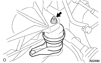
Install the engine mounting insulator LH with the nut.- Torque:
- 95 N*m{ 969 kgf*cm , 70 ft.*lbf }
For manual transaxle: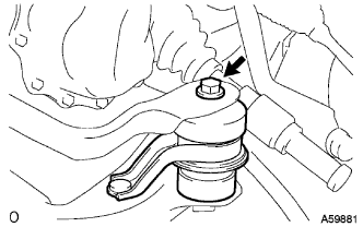
Install the engine mounting insulator LH with the bolt.- Torque:
- 143 N*m{ 1,459 kgf*cm , 105 ft.*lbf }
Install the engine mounting insulator RH with the nut.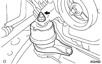
- Torque:
- 95 N*m{ 969 kgf*cm , 70 ft.*lbf }
Install the engine mounting insulator FR with the bolt.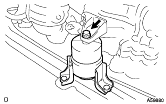
- Torque:
- 87 N*m{ 888 kgf*cm , 64 ft.*lbf }
For manual transaxle: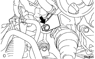
Install the engine lateral control rod with the bolt.- Torque:
- 89 N*m{ 910 kgf*cm , 66 ft.*lbf }
| 12. INSTALL VANE PUMP ASSEMBLY |
Install the vane pump to the engine with the 2 bolts.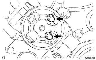
- Torque:
- 43 N*m{ 439 kgf*cm , 32 ft.*lbf }
Connect the oil pressure switch connector.
| 13. INSTALL ENGINE ASSEMBLY WITH TRANSAXLE |
Set the engine assembly with transaxle on the engine lifter.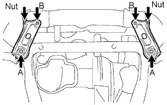
Install the engine assembly to the vehicle.
Install the frame side plate LH and RH with the 4 bolts and 2 nuts.
- Torque:
- Bolt A:
- 85 N*m{ 867 kgf*cm , 63 ft.*lbf }
- Bolt B and nut:
- 32 N*m{ 326 kgf*cm , 24 ft.*lbf }
Install the front suspension member brace rear RH and LH with the 4 bolts and 2 nuts.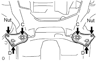
- Torque:
- Bolt C:
- 85 N*m{ 867 kgf*cm , 63 ft.*lbf }
- Bolt D and nut:
- 32 N*m{ 326 kgf*cm , 24 ft.*lbf }
| 14. INSTALL STEERING INTERMEDIATE SHAFT ASSEMBLY |
Align the matchmarks on the steering intermediate shaft assembly and the power steering link assembly.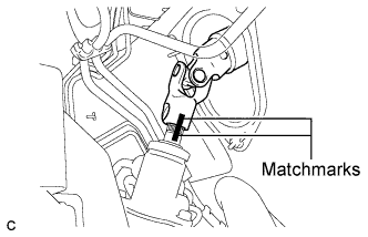
Install the bolt.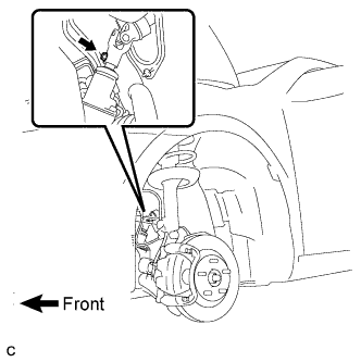
- Torque:
- 35 N*m{ 360 kgf*cm , 26 ft.*lbf }
Install the clamp to the steering column hole shield.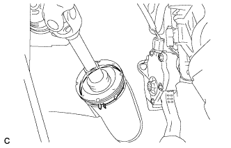
| 15. INSTALL FRONT AXLE ASSEMBLY LH |
Align the matchmarks and install the front drive shaft assembly to the front axle hub sub-assembly.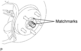
- NOTICE:
- Be careful not to damage the drive shaft boot and speed sensor rotor.
| 16. INSTALL FRONT AXLE ASSEMBLY RH |
- HINT:
- Use the same procedures described for the LH side.
| 17. INSTALL FRONT SUSPENSION LOWER NO. 1 ARM LH |
Install the lower ball joint to the front suspension lower No. 1 arm with the bolt and 2 nuts.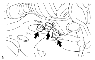
- Torque:
- 75 N*m{ 765 kgf*cm , 55 ft.*lbf }
| 18. INSTALL FRONT SUSPENSION LOWER NO. 1 ARM RH |
- HINT:
- Use the same procedures described for the LH side.
| 19. INSTALL TIE ROD ASSEMBLY LH |
Install the tie rod end sub-assembly to the steering knuckle with the nut.
- Torque:
- 49 N*m{ 500 kgf*cm , 36 ft.*lbf }
Install a new cotter pin.
- NOTICE:
- If the holes for the cotter pin are not aligned, tighten the nut up to 60° further.
| 20. INSTALL TIE ROD ASSEMBLY RH |
- HINT:
- Use the same procedures described for the LH side.
| 21. INSTALL FRONT SPEED SENSOR LH |
Install the front speed sensor to the steering knuckle with the bolt.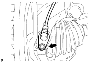
- Torque:
- 8.0 N*m{ 82 kgf*cm , 71 in.*lbf }
- NOTICE:
- Prevent foreign matter from adhering to the speed sensor.
- Be careful not to damage the speed sensor.
- Prevent foreign matter from adhering to the speed sensor.
Install the flexible hose and the speed sensor to the shock absorber with the bolt and set the sensor clip on the knuckle.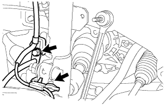
- Torque:
- 19 N*m{ 192 kgf*cm , 14 ft.*lbf }
- NOTICE:
- Be careful not to damage the speed sensor.
- Prevent foreign matter from adhering to the speed sensor.
- Do not twist the sensor wire when installing the speed sensor.
- Be careful not to damage the speed sensor.
| 22. INSTALL FRONT SPEED SENSOR RH |
- HINT:
- Use the same procedures described for the LH side.
| 23. INSTALL FRONT STABILIZER LINK ASSEMBLY LH |
Install the stabilizer link assembly with the nut.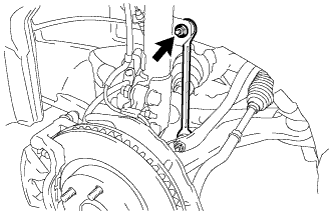
- Torque:
- 74 N*m{ 755 kgf*cm , 55 ft.*lbf }
- HINT:
- If the ball joint turns together with the nut, use a hexagon wrench (6 mm) to hold the stud.
| 24. INSTALL FRONT STABILIZER LINK ASSEMBLY RH |
- HINT:
- Use the same procedures described for the LH side.
| 25. INSTALL FRONT AXLE HUB NUT LH |
Using a socket wrench (30 mm), install a new axle hub nut.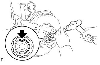
- Torque:
- 294 N*m{ 3,000 kgf*cm , 217 ft.*lbf }
Using a chisel and hammer, stake the front axle hub nut.
| 26. INSTALL FRONT AXLE HUB NUT RH |
- HINT:
- Use the same procedures described for the LH side.
| 27. INSTALL FRONT EXHAUST PIPE ASSEMBLY |
| 28. INSTALL COMPRESSOR AND PULLEY |
Install the compressor with the 4 bolts.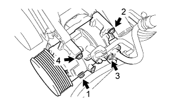
- Torque:
- 25 N*m{ 250 kgf*cm , 18 ft.*lbf }
- NOTICE:
- Tighten the bolts in the order shown in the illustration to install the cooler compressor.
| 29. INSTALL GENERATOR ASSEMBLY |
Confirm that the wire harness of the crankshaft position sensor is secured to the wire harness clamp bracket through the back of the rib of the timing chain cover.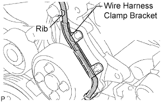
Install the generator assembly with the 2 bolts.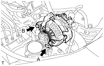
- Torque:
- Bolt A:
- 21 N*m{ 215 kgf*cm , 16 ft.*lbf }
- Bolt B:
- 52 N*m{ 530 kgf*cm , 38 ft.*lbf }
Install the generator wire to terminal B with the nut.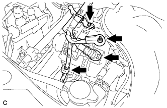
- Torque:
- 9.8 N*m{ 100 kgf*cm , 87 in.*lbf }
Install the clamp bracket with the bolt.
- Torque:
- 8.4 N*m{ 86 kgf*cm , 74 in.*lbf }
Attach the clamp and connect the generator connector to the generator.
| 30. CONNECT FUEL TUBE SUB-ASSEMBLY |
Push in the fuel tube connector to the fuel pipe until the connector makes a "click" sound.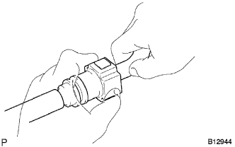
- NOTICE:
- Check for damage or contamination on the connected part of the pipe.
- Check if the pipe and the connector are securely connected by trying to pull them apart.
- Check for damage or contamination on the connected part of the pipe.
Install the No. 1 fuel pipe clamp.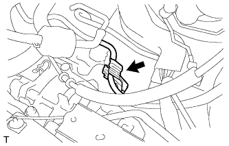
| 31. INSTALL CLUTCH RELEASE CYLINDER ASSEMBLY |
| 32. INSTALL CLUTCH ACCUMULATOR ASSEMBLY |
| 33. CONNECT RETURN TUBE SUB-ASSEMBLY |
Connect the return tube sub-assembly.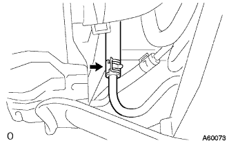
| 34. CONNECT NO. 1 OIL RESERVOIR TO PUMP HOSE |
Connect the No. 1 oil reservoir to pump hose.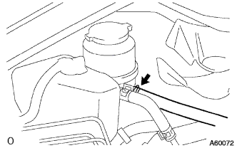
| 35. INSTALL TRANSMISSION CONTROL CABLE ASSEMBLY |
Connect the ends of the 2 cables and install the 2 washers and 2 clips.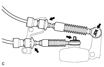
Install 2 new clips to the control cable bracket.
| 36. CONNECT ENGINE WIRE |
Install the 2 bolts and clamp to the body.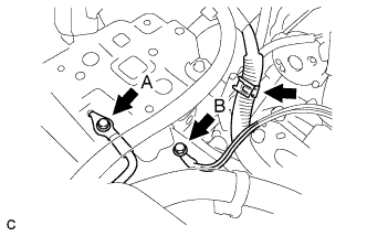
- Torque:
- Bolt A:
- 8.4 N*m{ 85 kgf*cm , 74 in.*lbf }
- Bolt B:
- 12 N*m{ 123 kgf*cm , 9 ft.*lbf }
Connect the clamp to the bracket.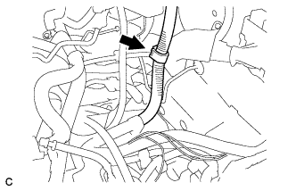
Connect the wire to the engine room junction block. Then, install it with the nut and 3 connectors.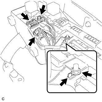
- Torque:
- 8.4 N*m{ 85 kgf*cm , 74 in.*lbf }
| 37. INSTALL ECM |
| 38. CONNECT HEATER WATER HOSE INLET |
Connect the heater inlet water hose.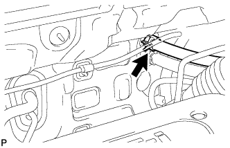
| 39. CONNECT HEATER WATER HOSE OUTLET |
Connect the heater outlet water hose.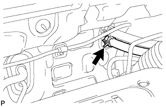
| 40. CONNECT RADIATOR HOSE INLET |
Install the clamp and connect the No. 1 radiator hose.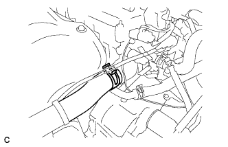
| 41. CONNECT RADIATOR HOSE OUTLET |
Install the clamp and connect the No. 2 radiator hose.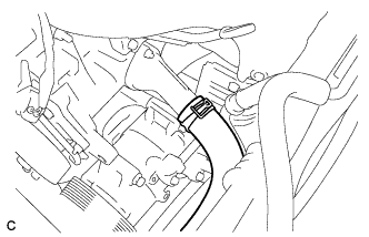
| 42. CONNECT NO. 1 VACUUM HOSE CONNECTOR |
Install the clamp and connect the No. 1 vacuum hose connector.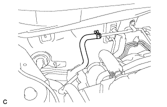
| 43. INSTALL NO. 2 ENGINE MOUNTING BRACKET RH |
Install the No. 2 engine mounting bracket RH with the 3 bolts.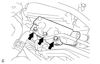
- Torque:
- 52 N*m{ 531 kgf*cm , 38 ft.*lbf }
| 44. INSTALL ENGINE MOVING CONTROL ROD SUB-ASSEMBLY |
Install the engine moving control rod with the 3 bolts.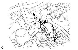
- Torque:
- 64 N*m{ 653 kgf*cm , 47 ft.*lbf }
Install the ground cable with the bolt.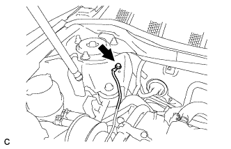
- Torque:
- 8.4 N*m{ 85 kgf*cm , 74 in.*lbf }
| 45. INSTALL NO. 2 ENGINE MOUNTING STAY RH |
Install the No. 2 engine mounting stay RH with the 2 bolts.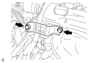
- Torque:
- 64 N*m{ 653 kgf*cm , 47 ft.*lbf }
| 46. INSTALL BATTERY |
Install the battery and battery tray.
Install the battery clamp with the bolt and nut.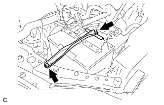
- Torque:
- Bolt:
- 9.0 N*m{ 92 kgf*cm , 80 in.*lbf }
- Nut:
- 3.5 N*m{ 36 kgf*cm , 31 in.*lbf }
| 47. INSTALL AIR CLEANER CASE SUB-ASSEMBLY |
Install the air cleaner case with the 3 bolts.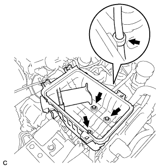
- Torque:
- 5.0 N*m{ 51 kgf*cm , 44 in.*lbf }
Connect the hose clamp.
| 48. INSTALL AIR CLEANER CAP SUB-ASSEMBLY |
Install the air cleaner filter element onto the air cleaner case.
Insert the hinges. Install the air cleaner cap sub-assembly with the 2 bolts.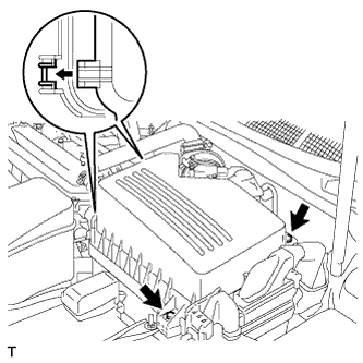
Connect the No. 1 air cleaner hose to the throttle body and unfasten the No. 1 air cleaner hose clamp.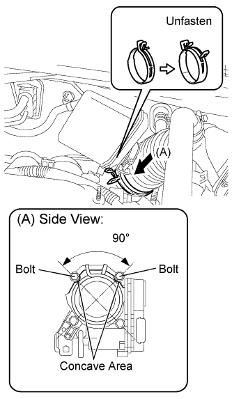
- NOTICE:
- Match each concave area concavity of the air cleaner hose with the bolt of the throttle body.
- Make sure that the hose clamp is at the correct angle.
- Match each concave area concavity of the air cleaner hose with the bolt of the throttle body.
Connect the No. 2 ventilation hose to the air cleaner hose.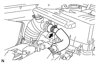
Connect the purge line hose to the clamp (*1).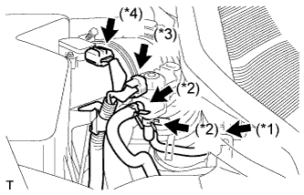
Connect the 2 purge VSV vacuum hoses (*2).
Connect the purge VSV connector (*3).
Connect the mass air flow meter connector (*4).
| 49. INSTALL AIR CLEANER INLET ASSEMBLY |
Install the air cleaner inlet with the 2 bolts.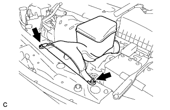
- Torque:
- 5.0 N*m{ 51 kgf*cm , 44 in.*lbf }
| 50. INSTALL V-RIBBED BELT |
Using SST and a 19 mm socket wrench, loosen the V-ribbed belt tensioner arm clockwise, then install the V-ribbed belt.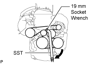
- SST
- 09216-42010
- NOTICE:
- Be sure to connect SST and the tools so that they are in line during use.
- When retracting the tensioner, turn it clockwise slowly for 3 seconds or more. Do not apply force rapidly.
- After the tensioner is fully retracted, do not apply more force than necessary.
- Be sure to connect SST and the tools so that they are in line during use.
After installing the V-ribbed belt, check that it fits properly in the ribbed grooves. Check to confirm that the belt has not slipped out of the grooves on the bottom of the crank pulley by hand.
| 51. INSTALL COWL TOP PANEL OUTER SUB-ASSEMBLY |
Install the outer cowl top panel sub-assembly with the 4 bolts and 4 nuts.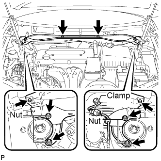
- Torque:
- Bolt:
- 5.0 N*m{ 51 kgf*cm , 44 in.*lbf }
- Nut:
- 85 N*m{ 867 kgf*cm , 63 ft.*lbf }
| 52. INSTALL WINDSHIELD WIPER MOTOR AND LINK ASSEMBLY |
| 53. INSTALL FRONT WHEEL |
- Torque:
- 103 N*m{ 1,050 kgf*cm , 76 ft.*lbf }
| 54. ADD ENGINE OIL |
| 55. CONNECT CABLE TO NEGATIVE BATTERY TERMINAL |
- Torque:
- 6.9 N*m{ 70 kgf*cm , 61 in.*lbf }
| 56. BLEED CLUTCH LINE |
Fill the brake reservoir with brake fluid and bleed the clutch system.
- Torque:
- 8.3 N*m{ 85 kgf*cm , 74 in.*lbf }
| 57. ADD ENGINE COOLANT |
Close the radiator drain cock plug and cylinder block drain cock plug.
- Torque:
- 13 N*m{ 130 kgf*cm , 9 ft.*lbf } for cylinder block drain cock plug
Slowly fill the radiator with TOYOTA Super Long Life Coolant (SLLC).
- Specified capacity:
- 6.7 liters (7.1 US qts, 5.9 lmp. qts)
- HINT:
- TOYOTA vehicles are filled with TOYOTA SLLC at the factory. In order to avoid damage to the engine cooling system and other technical problems, only use TOYOTA SLLC or similar high quality ethylene glycol based non-silicate, non-amine, non-nitrite, non-borate coolant with long-life hybrid organic acid technology (coolant with long-life hybrid organic acid technology consists of a combination of low phosphates and organic acids).
- TOYOTA vehicles are filled with TOYOTA SLLC at the factory. In order to avoid damage to the engine cooling system and other technical problems, only use TOYOTA SLLC or similar high quality ethylene glycol based non-silicate, non-amine, non-nitrite, non-borate coolant with long-life hybrid organic acid technology (coolant with long-life hybrid organic acid technology consists of a combination of low phosphates and organic acids).
- Contact your TOYOTA dealer for further details.
- Contact your TOYOTA dealer for further details.
Slowly pour coolant into the radiator reservoir tank until it reaches the FULL line.
Press the inlet and outlet radiator hoses several times by hand, and then check the level of the coolant.
If the coolant level is low, add coolant.
Install the radiator cap sub-assembly and reservoir tank cap.
Start the engine, and warm it up.
- HINT:
- Adjust the air conditioner set temperature to MAX (HOT).
Stop the engine, and wait until the engine coolant cools down.
Add engine coolant to the FULL line on the radiator reservoir.
| 58. ADD MANUAL TRANSAXLE OIL |
Park the vehicle on a level place.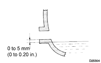
Remove the filler plug and gasket.
Check that the oil surface is within 5 mm (0.20 in.) below the lowest point of the filler plug opening.
- Oil grade:
- API GL-4 or GL-5
- Viscosity:
- SAE 75W-90
- NOTICE:
- Problems may occur if the oil level is too high or too low.
- After replacing the oil, drive the vehicle and check the oil level again.
- Problems may occur if the oil level is too high or too low.
- CAUTION:
- Oil may be hot take care not to scold your finger.
Check for oil leakage if the oil level is low.
Install the filler plug and a new gasket.
- Torque:
- 49 N*m{ 500 kgf*cm , 36 ft.*lbf }
| 59. ADD POWER STEERING FLUID |
| 60. BLEED POWER STEERING FLUID |
Check the fluid level (Click here).
Jack up the front of the vehicle and support it with stands.
Turn the steering wheel.
With the engine stopped, turn the steering wheel slowly from lock to lock several times.
Lower the vehicle.
Start the engine.
Run the engine at idle for a few minutes.
Turn the steering wheel.
With the engine idling, turn the steering wheel left or right to the full lock position and keep it in that position for 2 to 3 seconds, then turn the steering wheel to the opposite full lock position and keep it there for 2 to 3 seconds.
Repeat this procedure several times.
Stop the engine.
Check for foaming or emulsification.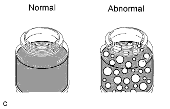
- HINT:
- If the system has to be bled twice because of forming or emulsification, be sure to check for fluid leaks in the system.
Check the fluid level (Click here).
| 61. INSPECT FOR FUEL LEAK |
- HINT:
- Click here.
| 62. INSPECT FOR ENGINE OIL LEAKS |
| 63. INSPECT FOR COOLANT LEAK |
- NOTICE:
- Before performing each inspection, turn the A/C switch OFF.
- CAUTION:
- Do not remove the radiator cap while the engine and radiator are still hot. Pressurized, hot engine coolant and steam may be released and cause serious burns.
Fill the radiator with coolant and attach a radiator cap tester.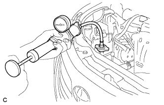
Warm up the engine.
Using a radiator cap tester, increase the pressure inside the radiator to 118 kPa (1.2 kgf*cm, 17 psi), and check that the pressure does not drop.
If the pressure drops, check the hoses, radiator and water pump for leaks. If no external leaks are found, check the heater core, cylinder block and cylinder head.
| 64. INSPECT FOR EXHAUST GAS LEAK |
| 65. ADJUST FRONT WHEEL ALIGNMENT |
| 66. INSPECT IGNITION TIMING |
Warm up the engine.
When using the intelligent tester: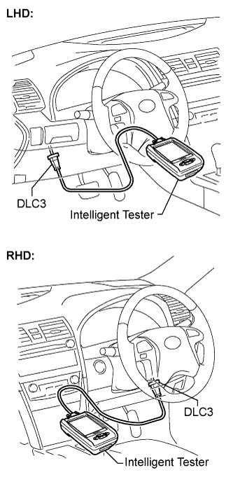
Check the ignition timing.Connect the intelligent tester to the DLC3.
Enter DATA LIST MODE on the intelligent tester.
- Ignition timing:
- 8 to 12° BTDC at idle
- HINT:
- Refer to the intelligent tester operator's manual for help when selecting the DATA LIST.
When not using the intelligent tester: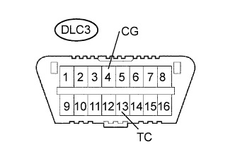
Check the ignition timing.Using SST, connect terminals 13 (TC) and 4 (CG) of the DLC3.
- SST
- 09843-18040
- NOTICE:
- Confirm the terminal numbers before connecting them. Connection with a wrong terminal can damage the electrical system.
- Turn off all electrical systems before connecting the terminals.
- Perform this inspection after the cooling fan motor has turned off.
- Confirm the terminal numbers before connecting them. Connection with a wrong terminal can damage the electrical system.
Remove the No. 1 engine cover.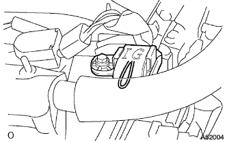
Pull out the wire harness as shown in the illustration. Connect the clip of the timing light to the wire harness.
- NOTICE:
- Use a timing light which can detect the first signal.
- After checking, be sure to tape the wire harness.
- Use a timing light which can detect the first signal.
Check the ignition timing at idle.
- Ignition timing:
- 8 to 12° BTDC at idle
- NOTICE:
- When checking the ignition timing, the transmission should be in neutral.
- HINT:
- After the engine rpm is kept at 1,000 to 1,300 rpm for 5 seconds, check that it returns to idle speed.
Disconnect terminals 13 (TC) and 4 (CG) of the DLC3.
Check the ignition timing at idle.
- Ignition timing:
- 5 to 15° BTDC at idle
Confirm that the ignition timing moves to the advanced angle side when the engine rpm is increased.
Remove the timing light.
Install the No. 1 engine cover.
| 67. INSPECT ENGINE IDLE SPEED |
Warm up the engine.
When using the intelligent tester:
Check the idle speed.Connect the intelligent tester to the DLC3.
- HINT:
- Refer to the intelligent tester operator's manual for further details.
Enter DATA LIST MODE on the intelligent tester.
- Idle speed:
Item
Specified Condition
Manual transmission
850 to 950 rpm
Automatic transmission
610 to 710 rpm
- NOTICE:
- When checking the idle speed, the transmission should be in neutral.
- Check the idle speed with the cooling fan off.
- Switch off all accessories and air conditioning before connecting the intelligent tester.
- When checking the idle speed, the transmission should be in neutral.
When not using the intelligent tester: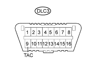
Check the idle speed.Using SST, connect the tachometer tester probe to terminal 9 (TAC) of the DLC3.
- SST
- 09843-18030
Check the idle speed.
- Idle speed:
Item
Specified Condition
Manual transmission
850 to 950 rpm
Automatic transmission
610 to 710 rpm
| 68. INSPECT CO/HC |
Start the engine.
Run the engine at 2,500 rpm for approximately 180 seconds.
Insert the CO/HC meter testing probe at least 40 cm (1.3 ft) into the tailpipe during idling.
Immediately check CO/HC concentration at idle and/at 2,500 rpm.
- HINT:
- Complete the measurement within 3 minutes.
- Check regulations and restrictions in your area when performing 2 mode CO/HC concentration testing (engine check at both idle speed and at 2,500 rpm).
- Complete the measurement within 3 minutes.
If the CO/HC concentration does not comply with regulations, troubleshoot in the order given below.
Check A/F sensor operation (Click here).
Check heated oxygen sensor operation (Click here).
See the table below for possible causes, and then inspect and repair.
CO
HC
Problems
Causes
Normal
High
Rough idle
- Faulty ignition:
- Incorrect timing
- Fouled, shorted, or improperly gapped plugs
- Incorrect valve clearance
- Leaking intake or exhaust valves
- Compression leaks from cylinders
Low
High
Rough idle
(fluctuating HC reading)
- Vacuum leaks:
- PCV hoses
- Intake manifold
- Throttle body
- Brake booster line
- Lean mixture causing misfire
High
High
Rough idle
(black smoke from exhaust)
- Restricted air filter
- Plugged PCV valve
- Faulty SFI system:
- Faulty pressure regulator
- Defective engine coolant temperature sensor
- Defective MAF meter
- Faulty ECM
- Faulty injectors
- Faulty throttle position sensor
- Faulty ignition:
| 69. INSTALL FRONT FENDER APRON SEAL RH |
| 70. INSTALL ENGINE UNDER COVER LH |
| 71. INSTALL ENGINE UNDER COVER RH |
| 72. INSTALL NO. 1 ENGINE COVER SUB-ASSEMBLY |
Install the engine cover with the 2 nuts.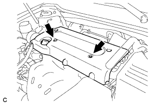
- Torque:
- 9.0 N*m{ 92 kgf*cm , 80 in.*lbf }
| 73. CHECK ABS SPEED SENSOR SIGNAL |
VSC: Click here.