Brake System
Brake
PRECAUTION
1. TROUBLESHOOTING PRECAUTION
-
NOTICE:
• Care must be taken to replace each part properly as it could affect the performance of the brake system and result in a driving hazard. Replace the parts with those having the same part number or equivalent.
• It is very important to keep parts and the area clean when repairing the brake system.
• Care must be taken when using magnets as they could affect the performance of the speed sensors.
• Since the brake line is classified as one of the critical safety related parts, disassemble the components if a brake fluid leak is found. If any abnormality is found, replace the component with a new one.
• When removing brake components, cover the brake tube connections to prevent foreign matter such as dust or dirt from entering the tubes.
• Do not damage or deform the brake tubes when removing or installing them.
• When installing a grommet to the body, ensure the brake tube passes through the centre of the grommet.
• When installing a brake tube or flexible hose, ensure it is free from twisting or bending.
• If the cap of the flexible hose does not match the groove on the bracket, twist the hose slightly to insert it.
• Flexible hoses must be free from oil, grease, etc.
• When installing a brake tube to a plastic clamp, ensure the brake tube is not loose or being pinched.
• Do not reuse a clip or plastic clamp removed from a flexible hose.
• After installing a brake tube and flexible hose, ensure they do not interfere with any other components.
• Do not allow brake fluid to contact to any painted surface such as the vehicle body. If brake fluid leaks onto any painted surface, immediately wash it off.
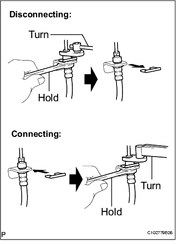
• Disconnect and connect the flexible hose and brake tube:
(a) Hold the flexible hose with a wrench and
disconnect the brake tube with a union nut wrench
without deforming the tube.
disconnect the brake tube with a union nut wrench
without deforming the tube.
(b) Remove the clip.
(c) Install a new clip.
(d) Connect the brake tube with a union nut wrench
without deforming the tube.
without deforming the tube.
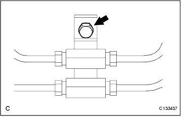
• Connect the brake tube and way:
(a) Support the way to prevent deformation of the
brake tube and connect the brake tube to the way
with a union nut wrench.
brake tube and connect the brake tube to the way
with a union nut wrench.
(b) Support the way to prevent deformation of the
brake tube and install the bolt to fix the way to the
body.
brake tube and install the bolt to fix the way to the
body.
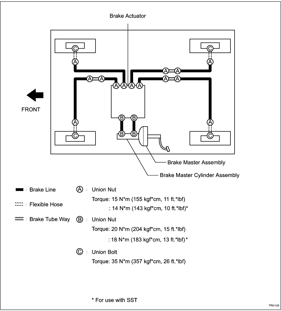
SYSTEM DIAGRAM
HINT:
See the layout drawing to confirm the locations and tightening torque of the flexible hoses and brake lines.
PROBLEM SYMPTOMS TABLE
Use the table below to help determine the cause of the problem. The numbers indicate the priority of the likely cause of the problem. Check each part in order. If necessary, replace these parts.
Low pedal or spongy pedal
|
1. Fluid leaks in brake system
|
Click Here |
2. Air in brake system
|
Click Here | |
3. Piston seals (Worn or damaged) (Front)
|
Click Here | |
4. Piston seals (Worn or damaged) (Rear)
|
Click Here | |
5. Master cylinder (Faulty)
|
Click Here | |
Brake drag
|
1. Brake pedal free play (Insufficient)
|
Click Here |
3. Parking brake pedal travel (Out of adjustment)
|
Click Here | |
4. Parking brake cable (Sticking)
|
Click Here | |
5. Parking brake shoe clearance (Out of adjustment)
|
Click Here | |
6. Pad (Cracked or distorted) (Front)
|
Click Here | |
7. Pad (Cracked or distorted) (Rear)
|
Click Here | |
8. Piston (Stuck) (Front)
|
Click Here | |
9. Piston (Stuck) (Rear)
|
Click Here | |
10. Piston (Seized) (Front)
|
Click Here | |
11. Piston (Seized) (Rear)
|
Click Here | |
12. Vacuum leaks in booster system
|
Click Here | |
13. Master cylinder (Faulty)
|
Click Here | |
Brake pull
|
1. Piston (Stuck) (Front)
|
Click Here |
2. Piston (Stuck) (Rear)
|
Click Here | |
3. Pad (Oily) (Front)
|
Click Here | |
4. Pad (Oily) (Rear)
|
Click Here | |
5. Piston (Seized) (Front)
|
Click Here | |
6. Piston (Seized) (Rear)
|
Click Here | |
7. Disc (Scored) (Front)
|
Click Here | |
8. Disc (Scored) (Rear)
|
Click Here | |
9. Pad (Cracked or distorted) (Front)
|
Click Here | |
10. Pad (Cracked or distorted) (Rear)
|
Click Here | |
Hard pedal but brake inefficient
|
1. Fluid leaks in brake system
|
Click Here |
2. Air in brake system
|
Click Here | |
3. Pad (Worn) (Front)
|
Click Here | |
4. Pad (Worn) (Rear)
|
Click Here | |
5. Pad (Cracked or distorted) (Front)
|
Click Here | |
6. Pad (Cracked or distorted) (Rear)
|
Click Here | |
7. Pad (Oily) (Front)
|
Click Here | |
8. Pad (Oily) (Rear)
|
Click Here | |
9. Pad (Glazed) (Front)
|
Click Here | |
10. Pad (Glazed) (Rear)
|
Click Here | |
11. Disc (Scored) (Front)
|
Click Here | |
12. Disc (Scored) (Rear)
|
Click Here | |
13. Vacuum leaks in booster system
|
Click Here | |
Noise from brakes
|
1. Pad (Cracked or distorted) (Front)
|
Click Here |
2. Pad (Cracked or distorted) (Rear)
|
Click Here | |
3. Cylinder mounting bolt (Loose) (Front)
|
Click Here | |
4. Caliper support bolt (Loose) (Rear)
|
Click Here | |
5. Disc (Scored) (Front)
|
Click Here | |
6. Disc (Scored) (Rear)
|
Click Here | |
7. Pad support plate (Loose) (Front)
|
Click Here | |
8. Pad support plate (Loose) (Rear)
|
Click Here | |
9. Sliding pin (Worn) (Front)
|
Click Here | |
10. Sliding pin (Worn) (Rear)
|
Click Here | |
11. Pad (Dirty) (Front)
|
Click Here | |
12. Pad (Dirty) (Rear)
|
Click Here | |
13. Pad (Glazed) (Front)
|
Click Here | |
14. Pad (Glazed) (Rear)
|
Click Here | |
15. Anti-squeal shim (Damaged) (Front)
|
Click Here | |
16. Anti-squeal shim (Damaged) (Rear)
|
Click Here |