REMOTE ENGINE STARTER SYSTEM > Remote Engine Starter does not Operate |
| 1.CHECK REMOTE ENGINE STARTER SYSTEM |
Check the remote engine starter function (Click here).
| Result | Proceed to |
| Engine does not start using remote engine start function | A |
| Engine does not stop using remote engine stop function | B |
|
| ||||
| A | |
 |
| 2.CHECK DTC OUTPUT (CAN COMMUNICATION SYSTEM) |
Check if CAN communication DTCs are output (Click here).
|
| ||||
| OK | |
|
| 3.CHECK DTC OUTPUT (HEALTH CHECK) |
Connect the Techstream to the DLC3.
Turn the engine switch on (IG).
Enter the following menus: System Select / Health Check.
| Result | Proceed to |
| DTCs are not output | A |
| DTCs are output | B |
|
| ||||
| A | |
|
| 4.CHECK DIAGNOSTIC FACTOR INDICATION |
Enter diagnostic mode (Click here).
Check the engine stop factor.
|
| ||||
| OK | ||
 | ||
| ||
| 5.CHECK ENGINE STOP FACTOR (HAZARD WARNING LIGHT FLASHING PATTERN) |
Check the engine stop factor.
| Result | Proceed to |
| Hazard warning lights flash 3 times (Engine speed is too high or low) [for 2GR-FE] | A |
| Hazard warning lights flash 3 times (Engine speed is too high or low) [for 2AR-FE] | B |
| Hazard warning lights flash 7 or 8 times (Brake pedal is pushed or vehicle speed is abnormal) | C |
| Hazard warning lights flash 9 times (Immobiliser collation discrepancy) | D |
| Except above (Other engine stop factor) | E |
|
| ||||
|
| ||||
|
| ||||
|
| ||||
| A | ||
| ||
| ||
| 6.CONFIRM OTHER ENGINE STOP FACTOR |
Confirm the engine stop factor and the vehicle condition.
|
| ||||
| OK | |
|
| 7.CHECK ENGINE START FUNCTION (FUEL LEVEL REMAINS IN THE TANK) |
Check that the fuel remaining in the tank is enough to start the engine or not.
|
| ||||
| OK | |
|
| 8.CHECK CRANKING FUNCTION (REMOTE ENGINE START FUNCTION) |
Perform the remote engine start operation (Click here).
Check if the engine cranks using the remote engine start function.
| Result | Proceed to |
| Engine cranks | A |
| Engine does not crank | B |
|
| ||||
| A | |
|
| 9.CHECK WIRELESS DOOR LOCK CONTROL SYSTEM |
Check the wireless door lock control functions using the electrical key transmitter sub-assembly (Click here).
|
| ||||
| OK | |
|
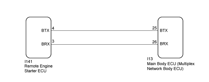
| 10.CHECK HARNESS AND CONNECTOR (MAIN BODY ECU (MULTIPLEX NETWORK BODY ECU) - REMOTE ENGINE STARTER ECU) |
Disconnect the I13 main body ECU (multiplex network body ECU) connector.
Disconnect the I141 remote engine starter ECU connector.
Measure the resistance according to the value(s) in the below.
| Tester Connection | Condition | Specified condition |
| I13-25 (BTX) - I141-4 (BTX) | Always | Below 1 Ω |
| I13-26 (BRX) - I141-3 (BRX) | Always | Below 1 Ω |
| I13-25 (BTX) - Body ground | Always | 10 KΩ or higher |
| I13-26 (BRX) - Body ground | Always | 10 KΩ or higher |
|
| ||||
| OK | |
|
| 11.CHECK REMOTE ENGINE STARTER ECU (OUTPUT SIGNAL) |
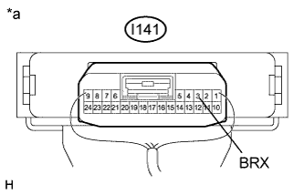 |
Reconnect the I141 remote engine starter ECU connector.
Using an oscilloscope, check the waveform.
| Item | Content |
| Tester Connection | I141-3 (BRX) - Body ground |
| Tool Setting | 5 V/DIV., 20 ms./DIV. |
| Condition | Remote engine start function is operated |
| *a | Component with harness connected (Remote Engine Starter ECU) |
|
| ||||
| OK | ||
| ||
| ||
| 12.CHECK ENGINE STOP FUNCTION |
Check if the engine stops when any of the following conditions is met.
|
| ||||
| OK | |
|
| 13.CHECK WIRELESS DOOR LOCK CONTROL SYSTEM |
Check the wireless door lock control functions using the electrical key transmitter sub-assembly (Click here).
|
| ||||
| OK | ||
| ||
| ||

