2GR-FE INTAKE / EXHAUST EXHAUST MANIFOLD INSTALLATION
PROCEDURE

 17105
1.INSTALL EXHAUST MANIFOLD SUB-ASSEMBLY LH
Set a new gasket to the cylinder head sub-assembly.
Temporarily install the exhaust manifold sub-assembly LH with the 6 nuts.
Temporarily install the No. 2 manifold stay with the bolt and nut.
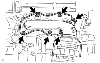
Using a 12 mm deep socket wrench, in several steps, uniformly tighten the 6 nuts in the order shown in the illustration.
- Torque:
- 21 N*m (214 kgf*cm, 15 ft.*lbf)
17119
2.INSTALL NO. 2 MANIFOLD STAY
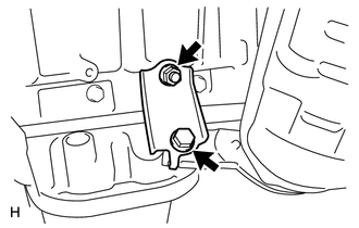
Tighten the bolt and nut in the order shown in the illustration.
- Torque:
- 34 N*m (347 kgf*cm, 25 ft.*lbf)
17168
3.INSTALL NO. 2 EXHAUST MANIFOLD HEAT INSULATOR
Install the No. 2 exhaust manifold heat insulator with the 3 bolts.
- Torque:
- 8.5 N*m (87 kgf*cm, 75 in.*lbf)
12142
4.INSTALL NO. 2 ENGINE OIL LEVEL DIPSTICK GUIDE
89467B
5.INSTALL AIR FUEL RATIO SENSOR (for Bank 2)
17104
6.INSTALL EXHAUST MANIFOLD SUB-ASSEMBLY RH
Set a new gasket to the cylinder head sub-assembly.
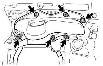
Using a 12 mm deep socket wrench, install the exhaust manifold sub-assembly RH by tightening the 6 nuts in the order shown in the illustration.
- Torque:
- 21 N*m (214 kgf*cm, 15 ft.*lbf)
89467B
7.INSTALL AIR FUEL RATIO SENSOR (for Bank 1)
17410
8.INSTALL FRONT EXHAUST PIPE ASSEMBLY
Install 3 new gaskets to the front exhaust pipe assembly.
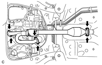
| *1 | Bolt |
| *2 | Nut |
| *3 | Bolt and Nut |
Install the front exhaust pipe assembly with the 4 bolts and 4 nuts.
- Torque:
- Bolt : 55 N*m (561 kgf*cm, 40 ft.*lbf)
- Nut : 55 N*m (561 kgf*cm, 40 ft.*lbf)
- Bolt and Nut : 49 N*m (500 kgf*cm, 36 ft.*lbf)
Install the No. 1 exhaust pipe support bracket with the 2 bolts (for Rear Side).
- Torque:
- 33 N*m (337 kgf*cm, 24 ft.*lbf)
Connect the 2 heated oxygen sensor connectors.
Install the 2 wire harnesses to the clamp.
17584B
9.INSTALL NO. 1 EXHAUST PIPE SUPPORT BRACKET (for Front Side)
16470
10.INSTALL RADIATOR RESERVE TANK ASSEMBLY
51441C
11.INSTALL ENGINE UNDER COVER RH
53851Z
12.INSTALL FRONT WHEEL OPENING EXTENSION PAD RH
13.INSPECT FOR EXHAUST GAS LEAK