PARKING BRAKE PARKING BRAKE ASSEMBLY DISASSEMBLY
CAUTION / NOTICE / HINT
- NOTICE:
- ·
When the brake pedal is first depressed after replacing the brake pads or pushing back the disc brake piston, DTC C1214 may be output. As there is no malfunction, clear the DTC.
·While the auxiliary battery is connected, even if the power switch is off, the brake control system activates when the brake pedal is depressed or the door courtesy switch is turned on. Therefore, even if only brake pads are to be removed and installed, be sure to perform the Disable Brake Control procedure and disconnect the cable from the negative (-) terminal of the auxiliary battery before beginning work.
- HINT:
- ·
Use the same procedure for the RH side and LH side.
·The following procedure is for the LH side.
PROCEDURE

 1. PRECAUTION
- NOTICE:
-
After turning the power switch off, waiting time may be required before disconnecting the cable from the negative (-) auxiliary battery terminal, Therefore, make sure to read the disconnecting the cable from the negative (-) auxiliary battery terminal notice before proceeding with work.
-
Click hereGeneral>INTRODUCTION>REPAIR INSTRUCTION>PRECAUTION
2.REMOVE WINDSHIELD WIPER MOTOR AND LINK ASSEMBLY
55702A
3.REMOVE FRONT OUTER COWL TOP PANEL SUB-ASSEMBLY
4. DISABLE BRAKE CONTROL
5.REMOVE REAR WHEEL
6.SEPARATE REAR DISC BRAKE CALIPER ASSEMBLY
42491
7.REMOVE PARKING BRAKE SHOE ADJUSTING HOLE PLUG
42431
8.REMOVE REAR DISC
Click hereBrake>BRAKE (REAR)>REAR BRAKE>REMOVAL
46550G
9.REMOVE PARKING BRAKE SHOE RETURN TENSION SPRING (for Upper Side)
for Rear Side:
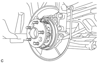
Remove the parking brake shoe return tension spring.
for Front Side:
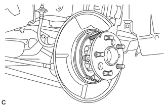
Remove the parking brake shoe return tension spring.
47614
10.REMOVE PARKING BRAKE SHOE STRUT
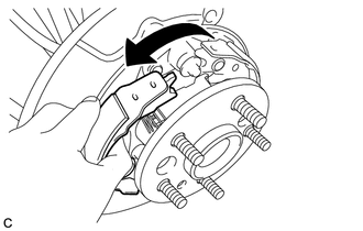
Pull the No. 1 parking brake shoe assembly towards the front of the vehicle by hand as shown in the illustration.
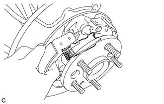
Remove the parking brake shoe strut.
47613D
11.REMOVE PARKING BRAKE SHOE STRUT COMPRESSION SPRING
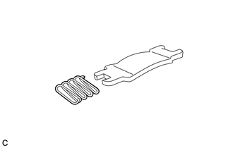
Remove the parking brake shoe strut compression spring.
46580
12.SEPARATE NO. 1 PARKING BRAKE SHOE ASSEMBLY
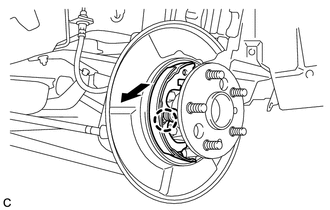
Release the claw of the parking brake shoe hold down spring cup and separate the No. 1 parking brake shoe assembly.
46590
13.SEPARATE NO. 2 PARKING BRAKE SHOE ASSEMBLY
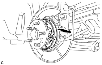
Release the claw of the parking brake shoe hold down spring cup and separate the No. 2 parking brake shoe assembly.
47406A
14.REMOVE PARKING BRAKE SHOE ADJUSTING SCREW SET
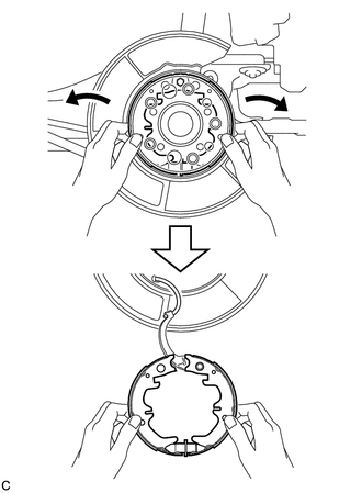
Expand the No. 1 and No. 2 parking brake shoe assemblies outward by hand and pull downward to separate them from the parking brake plate.
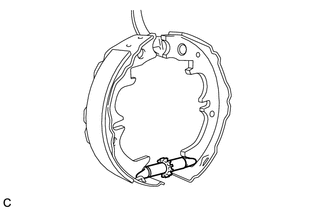
Remove the parking brake shoe adjusting screw set.
46580
15.REMOVE NO. 1 PARKING BRAKE SHOE ASSEMBLY
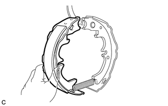
Remove the No. 1 parking brake shoe assembly.
46550E
16.REMOVE PARKING BRAKE SHOE RETURN TENSION SPRING (for Lower Side)
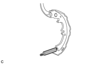
Remove the parking brake shoe return tension spring.
47612
17.SEPARATE PARKING BRAKE SHOE LEVER
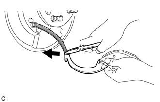
Using needle-nose pliers, separate the parking brake shoe lever from the No. 3 parking brake cable assembly.
47612
18.REMOVE PARKING BRAKE SHOE LEVER
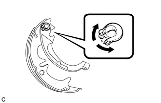
Using a screwdriver, remove the parking brake shoe type C washer, parking brake shoe shim and the parking brake shoe lever.
- HINT:
-
Parking brake shoe shims are provided when necessary to adjust the clearance between the parking brake shoe lever and parking brake shoe type C washer. Some vehicles may not be equipped with shims.
47447E
19.REMOVE PARKING BRAKE SHOE HOLD DOWN SPRING PIN
for Front Side:
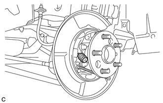
Remove the 2 parking brake shoe hold down spring cups, parking brake shoe hold down spring and parking brake shoe hold down spring pin.
for Rear Side:
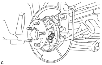
Remove the 2 parking brake shoe hold down spring cups, parking brake shoe hold down spring and parking brake shoe hold down spring pin.
47456A
20.REMOVE PARKING BRAKE SHOE GUIDE PLATE
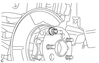
Remove the parking brake shoe guide plate set bolt and the parking brake shoe guide plate.