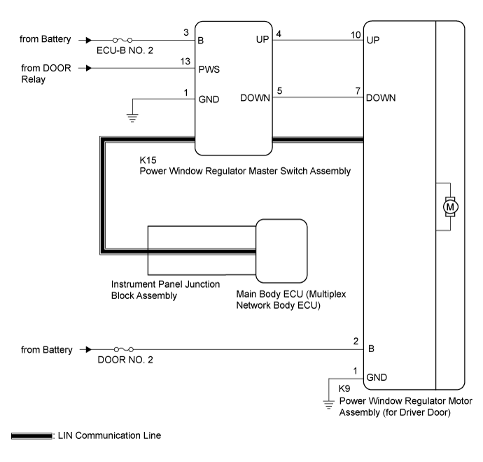
POWER WINDOW CONTROL SYSTEM (for Models with Jam Protection Function on Front Door Windows) > Driver Side Power Window does not Operate with Power Window Master Switch |
| 1.READ VALUE USING GTS (MAIN BODY) |
Connect the GTS to the DLC3.
Turn the engine switch on (IG).
Turn the GTS on.
Enter the following menus: Body Electrical / Main Body / Data List.
Read the Data List according to the display on the GTS.
| Tester Display | Measurement Item/Range | Normal Condition | Diagnostic Note |
| Communication D-Door Motor | Connection status between power window regulator motor assembly (for driver door) and main body ECU (multiplex network body ECU) / STOP or OK | STOP: Communication stopped OK: Normal communication | - |
| Communication Master SW | Connection status between power window regulator master switch assembly and main body ECU (multiplex network body ECU) / STOP or OK | STOP: Communication stopped OK: Normal communication | - |
|
| ||||
| OK | |
 |
| 2.READ VALUE USING GTS (D-DOOR MOTOR) |
Enter the following menus: Body Electrical / D-Door Motor / Data List.
Read the Data List according to the display on the GTS.
| Tester Display | Measurement Item/Range | Normal Condition | Diagnostic Note |
| D Door P/W Up SW | Driver door power window manual up switch signal / OFF or ON | OFF: Driver door power window manual up switch not being operated ON: Driver door power window manual up switch being operated | - |
| D Door P/W Down SW | Driver door power window manual down switch signal / OFF or ON | OFF: Driver door power window manual down switch not being operated ON: Driver door power window manual down switch being operated | - |
|
| ||||
| OK | |
|
| 3.PERFORM ACTIVE TEST USING GTS (D-DOOR MOTOR) |
Enter the following menus: Body Electrical / D-Door Motor / Active Test.
Perform the Active Test according to the display on the GTS.
| Tester Display | Test Part | Control Range | Diagnostic Note |
| Power Window | Power window | OFF / DOWN / UP | - |
|
| ||||
| OK | ||
 | ||
| ||
| 4.CHECK HARNESS AND CONNECTOR (POWER WINDOW REGULATOR MASTER SWITCH ASSEMBLY - POWER WINDOW REGULATOR MOTOR ASSEMBLY (FOR DRIVER DOOR)) |
Disconnect the K15 power window regulator master switch assembly connector.
Disconnect the K9 power window regulator motor assembly (for driver door) connector.
Measure the resistance according to the value(s) in the table below.
| Tester Connection | Condition | Specified Condition |
| K15-4 (UP) - K9-10 (UP) | Always | Below 1 Ω |
| K15-4 (UP) or K9-10 (UP) - Body ground | Always | 10 kΩ or higher |
| K15-5 (DOWN) - K9-7 (DOWN) | Always | Below 1 Ω |
| K15-5 (DOWN) or K9-7 (DOWN) - Body ground | Always | 10 kΩ or higher |
|
| ||||
| OK | |
|
| 5.REPLACE POWER WINDOW REGULATOR MASTER SWITCH ASSEMBLY |
Replace the power window regulator master switch assembly (Click here).
| NEXT | |
|
| 6.CHECK MANUAL UP / DOWN FUNCTION (FOR DRIVER DOOR) |
Check that the driver door power window moves when the manual up and down function of the power window regulator master switch assembly is operated (Click here).
|
| ||||
| OK | ||
| ||
| ||

