 |
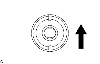
Temporarily install a new rear suspension member body mounting front cushion LH to the position shown in the illustration.
 | Front of the Vehicle |
REAR SUSPENSION MEMBER (for TMC, TMMR Made) > INSTALLATION |
| 1. INSTALL HOLE PLUG |
Install the 3 hole plugs to the rear suspension member sub-assembly.
| 2. INSTALL REAR SUSPENSION MEMBER BODY MOUNTING FRONT CUSHION LH |
|
Temporarily install a new rear suspension member body mounting front cushion LH to the position shown in the illustration.
| Front of the Vehicle |
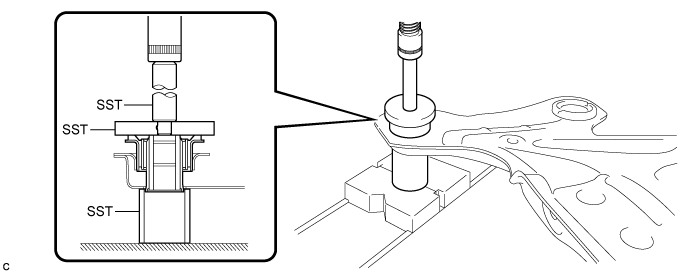
Using SST and a press, install the rear suspension member body mounting front cushion LH to the rear suspension member sub-assembly.
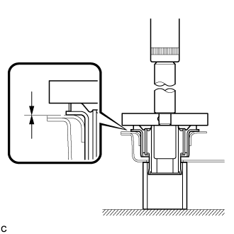 |
While observing from the side, press in the rear suspension member body mounting front cushion LH until there is no clearance between the rear suspension member body mounting front cushion LH and the rear suspension member sub-assembly as shown in the illustration.
| 3. INSTALL REAR SUSPENSION MEMBER BODY MOUNTING FRONT CUSHION RH |
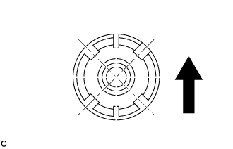 |
Temporarily install a new rear suspension member body mounting front cushion RH to the position shown in the illustration.
| Front of the Vehicle |
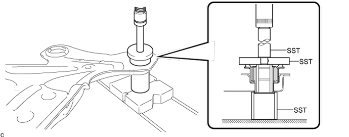
Using SST and a press, install the rear suspension member body mounting front cushion RH to the rear suspension member sub-assembly.
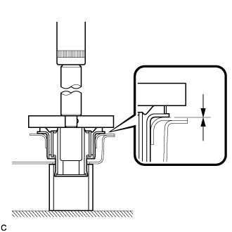 |
While observing from the side, press in the rear suspension member body mounting front cushion RH until there is no clearance between the rear suspension member body mounting front cushion RH and the rear suspension member sub-assembly as shown in the illustration.
| 4. INSTALL REAR SUSPENSION MEMBER BODY MOUNTING REAR CUSHION (for LH Side) |
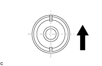 |
Temporarily install a new rear suspension member body mounting rear cushion (LH side) to the position shown in the illustration.
| Front of the Vehicle |
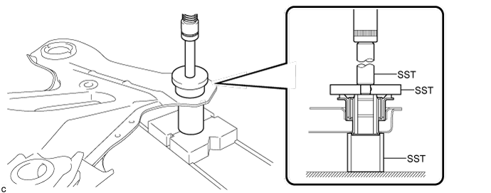
Using SST and a press, install the rear suspension member body mounting rear cushion (LH side) to the rear suspension member sub-assembly.
|
While observing from the side, press in the rear suspension member body mounting rear cushion (LH side) until there is no clearance between the rear suspension member body mounting rear cushion (LH side) and the rear suspension member sub-assembly as shown in the illustration.
| 5. INSTALL REAR SUSPENSION MEMBER BODY MOUNTING REAR CUSHION (for RH Side) |
| 6. INSTALL REAR SUSPENSION MEMBER DAMPER (w/ Dynamic Damper) |
Install the rear suspension member damper to the rear suspension member sub-assembly with the 2 bolts.
| 7. INSTALL REAR NO. 1 SUSPENSION ARM ASSEMBLY LH |
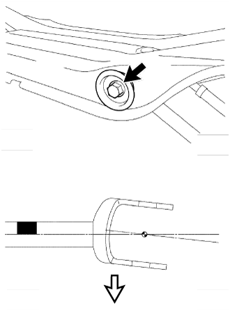 |
Temporarily tighten the rear No. 1 suspension arm assembly LH (inner side) with the bolt.
| Bolt |
 | Front of the Vehicle |
 | Paint Mark |
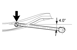 |
Set the rear No.1 suspension arm assembly in the position shown in the illustration, and fully tighten the bolt.
| 8. INSTALL REAR NO. 1 SUSPENSION ARM ASSEMBLY RH |
| 9. TEMPORARILY TIGHTEN REAR NO. 2 SUSPENSION ARM ASSEMBLY LH |
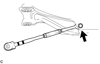 |
Temporarily tighten the rear No. 2 suspension arm assembly LH (inside) with the bolt.
| Bolt |
| Paint Mark |
| 10. TEMPORARILY TIGHTEN REAR NO. 2 SUSPENSION ARM ASSEMBLY RH |
| 11. INSTALL REAR SUSPENSION MEMBER SUB-ASSEMBLY |
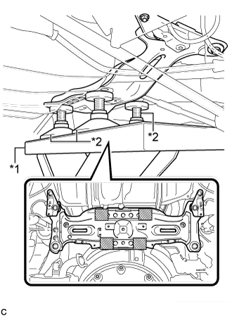 |
Support the rear suspension member sub-assembly with an engine lifter using 4 attachments or equivalent tools.
| *1 | Engine Lifter |
| *2 | Attachment |
 | Attachment Placement Location |
Raise the rear suspension member sub-assembly until there is no clearance between the rear suspension member sub-assembly and the vehicle body.
Install the rear suspension member sub-assembly, rear suspension member lower stopper sub-assembly LH and rear suspension member lower stopper sub-assembly RH with the 4 nuts.
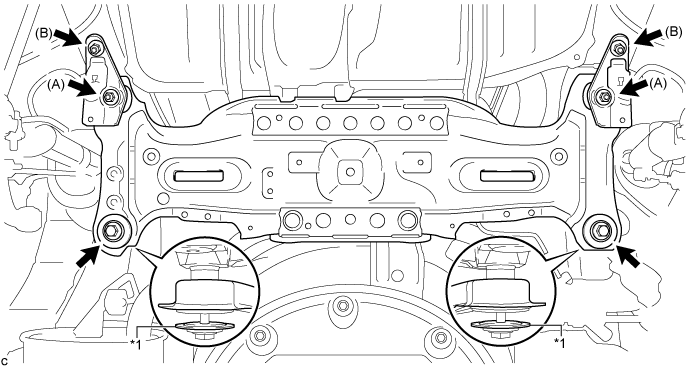
| *1 | Rear suspension member lower stopper | - | - |
Install the 2 rear suspension member lower stoppers with the 2 bolts to the rear suspension member sub-assembly.
| 12. INSTALL NO. 3 EXHAUST PIPE SUPPORT BRACKET |
Install the No. 3 exhaust pipe support bracket to the rear suspension member sub-assembly with the 2 bolts.
| 13. INSTALL REAR BODY END MOUNTING BRACKET SUB-ASSEMBLY |
Install the rear body end mounting bracket sub-assembly to the rear suspension member sub-assembly with the 2 bolts.
| 14. CONNECT REAR NO. 1 SUSPENSION ARM ASSEMBLY LH |
Temporarily tighten the rear No. 1 suspension arm assembly (outer side) to the rear axle carrier sub-assembly with the bolt and nut.
| 15. CONNECT REAR NO. 1 SUSPENSION ARM ASSEMBLY RH |
| 16. CONNECT REAR NO. 2 SUSPENSION ARM ASSEMBLY LH |
Temporarily tighten the rear No. 2 suspension arm assembly (outer side) to the rear axle carrier sub-assembly with the bolt and nut.
| 17. CONNECT REAR NO. 2 SUSPENSION ARM ASSEMBLY RH |
| 18. INSTALL REAR STABILIZER BAR |
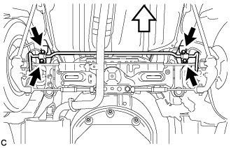 |
Install the rear stabilizer bar with the 4 bolts.
| Bolt |
| Front of the Vehicle |
| 19. CONNECT REAR STABILIZER LINK ASSEMBLY LH |
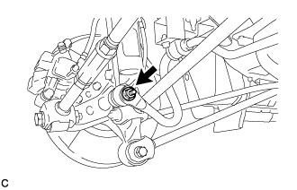 |
Connect the rear stabilizer link assembly LH to the rear stabilizer bar with nut.
| 20. CONNECT REAR STABILIZER LINK ASSEMBLY RH |
| 21. STABILIZE SUSPENSION |
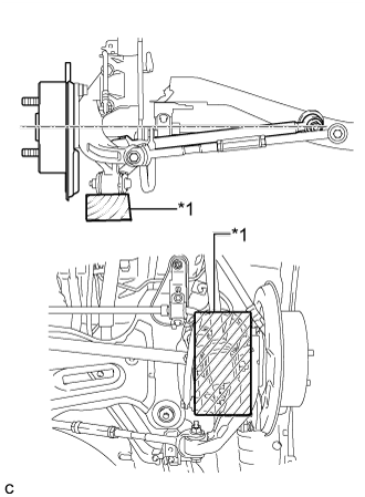 |
Jack up the rear axle carrier sub-assembly, placing a wooden block under it to avoid damage. Apply load to the suspension so that the installed bolt of the rear No. 1 suspension arm assembly (inner side) is horizontally aligned with the center of the rear axle hub.
| *1 | Wooden Block |
| 22. FULLY TIGHTEN REAR NO. 1 SUSPENSION ARM ASSEMBLY LH |
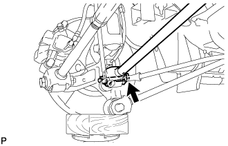 |
Fully tighten the bolt.
| 23. FULLY TIGHTEN REAR NO. 1 SUSPENSION ARM ASSEMBLY RH |
| 24. FULLY TIGHTEN REAR NO. 2 SUSPENSION ARM ASSEMBLY LH |
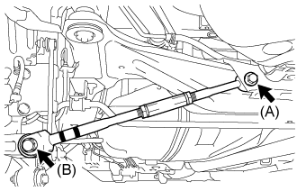 |
Fully tighten the bolt (A).
Fully tighten the bolt (B).
| 25. FULLY TIGHTEN REAR NO. 2 SUSPENSION ARM ASSEMBLY RH |
| 26. INSTALL REAR HEIGHT CONTROL SENSOR SUB-ASSEMBLY (w/ Height Control Sensor) |
| 27. INSTALL CENTER EXHAUST PIPE ASSEMBLY |
| 28. INSTALL NO. 2 FLOOR UNDER COVER |
for TMC Made:
Install the No. 2 floor under cover with the 6 nuts.
Install the screw and 2 clips.
for TMMR Made:
Install the No. 2 floor under cover with the 6 nuts.
Install the 2 clips.
| 29. INSTALL NO. 1 FLOOR UNDER COVER |
for TMC Made:
Install the No. 1 floor under cover with the 5 nuts and 2 clips.
Install the screw.
for TMMR Made:
Install the No. 1 floor under cover with the 5 nuts and 2 clips.
| 30. INSTALL REAR WHEELS |
| 31. INSPECT AND ADJUST REAR WHEEL ALIGNMENT |
| 32. INITIALIZE HEIGHT CONTROL SENSOR SIGNAL (w/ Height Control Sensor) |
| 33. ADJUST HEADLIGHT AIMING (w/ Height Control Sensor) |