 |
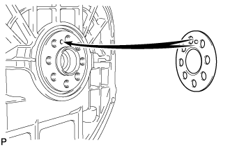
Install the front drive plate spacer.
- HINT:
- Align the pin of the front drive plate spacer with the pin hole of the crankshaft.
ENGINE ASSEMBLY > INSTALLATION |
| 1. REMOVE ENGINE STAND |
| 2. INSTALL DRIVE PLATE AND RING GEAR SUB-ASSEMBLY |
Using SST, hold the crankshaft pulley.
Clean the 8 bolts and 8 bolt holes.
|
Install the front drive plate spacer.
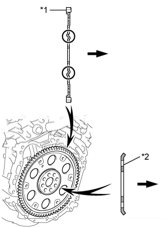 |
Install the drive plate and ring gear sub-assembly and rear drive plate spacer onto the crankshaft.
| *1 | Drive Plate |
| *2 | Rear Spacer |
 | Transaxle Side |
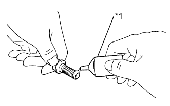 |
Apply adhesive to 2 or 3 threads of each bolt.
| *1 | Adhesive |
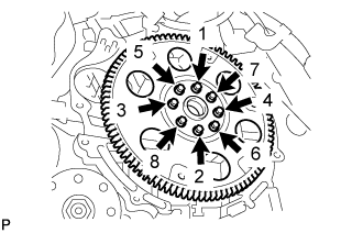 |
In several steps, uniformly install and tighten the 8 bolts in the sequence shown in the illustration.
| 3. INSTALL DRIVE SHAFT BEARING BRACKET |
Install the drive shaft bearing bracket with the 3 bolts.
| 4. INSTALL ENGINE MOUNTING BRACKET RH |
Install the engine mounting bracket RH with the 3 bolts.
| 5. INSTALL AUTOMATIC TRANSAXLE ASSEMBLY |
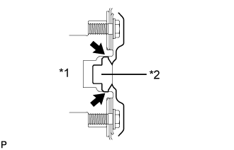 |
Apply clutch spline grease to the surface of the crankshaft that contacts the torque converter centerpiece.
| *1 | Crankshaft |
| *2 | Torque Converter Centerpiece |
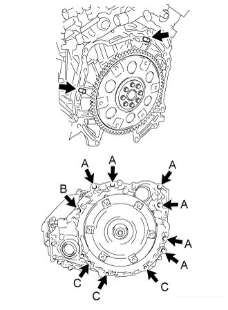 |
While keeping the engine and automatic transaxle assembly horizontal, align the knock pins with the holes in the automatic transaxle assembly and install the 10 bolts shown in the illustration.
Clean and degrease the bolt and the installation hole in the automatic transaxle.
Apply a few drops of adhesive to 2 or 3 threads at the tip of each of the bolt.
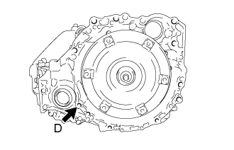 |
Install the bolt.
| 6. INSTALL ENGINE WIRE |
Install the engine wire to the engine with transaxle.
| 7. INSTALL FRONT ENGINE MOUNTING INSULATOR ASSEMBLY |
Temporarily install the front engine mounting insulator assembly with the 3 bolts.
| 8. INSTALL ENGINE MOUNTING INSULATOR LH |
Temporarily install the engine mounting insulator LH with the 3 bolts.
| 9. INSTALL ENGINE MOUNTING INSULATOR RH |
Temporarily install the engine mounting insulator RH with the 3 bolts.
| 10. INSTALL FRONT FRAME ASSEMBLY |
Install the engine mounting insulator RH with the nut.
Install the engine mounting insulator LH with the nut.
Install the front engine mounting insulator assembly with the bolt.
Connect the 2 wire clamps and vacuum switching valve connector.
Connect the 2 wire clamps and oil pressure switch connector.
Fully tighten the 9 temporarily installed nuts of the engine mounting insulators to the specified torque.
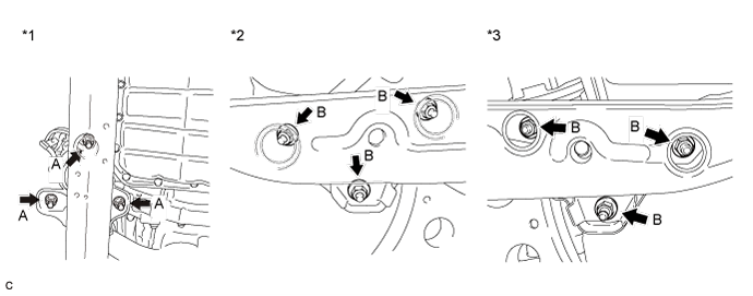
| *1 | Front Engine Mounting Insulator Assembly | *2 | Engine Mounting Insulator RH |
| *3 | Engine Mounting Insulator LH | - | - |
Install the 4 hole plugs.
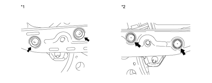
| *1 | Engine Mounting Insulator RH | *2 | Engine Mounting Insulator LH |
| 11. INSTALL COMPRESSOR AND MAGNETIC CLUTCH |
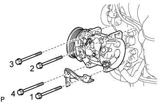 |
Install the compressor and magnetic clutch and bracket with the 4 bolts.
| 12. INSTALL GENERATOR ASSEMBLY |
Install the generator assembly with the 2 bolts.
Connect the wire harness clamp.
Install the generator bracket with the 2 bolts.
Connect the generator connector to the generator assembly.
Install the generator wire with the bolt.
Install the nut and connect the wire harness to terminal B.
Install the terminal cap.
| 13. INSTALL V-RIBBED BELT |
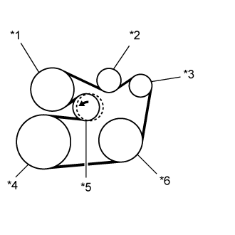 |
Install the V-ribbed belt.
| *1 | Water Pump |
| *2 | Idler |
| *3 | Generator |
| *4 | Crankshaft |
| *5 | Tensioner |
| *6 | A/C Compressor |
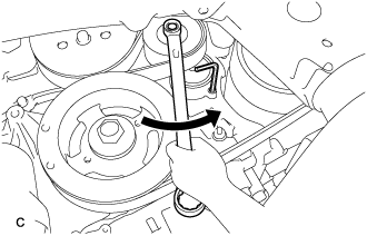 |
Turn the V-ribbed belt tensioner counterclockwise and remove the 5 mm hexagon wrench.
After installing the V-ribbed belt, check that it fits properly in the ribbed grooves. Confirm that the belt has not slipped out of the grooves on the bottom of the crank pulley by hand.
| 14. INSTALL ENGINE ASSEMBLY WITH TRANSAXLE |
Set the engine assembly with transaxle on an engine lifter.
Remove the engine hangers .
Install the engine assembly with transaxle to the vehicle.
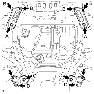 |
Install the frame side rail plates RH and LH with the 4 bolts and 2 nuts.
Install the front suspension member rear braces RH and LH with the 4 bolts and 2 nuts.
| 15. INSTALL DRIVE PLATE AND TORQUE CONVERTER SETTING BOLT |
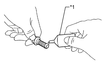 |
Apply a few drops of adhesive to 2 or 3 threads at the tip of each of the 6 torque converter setting bolts.
| *1 | Adhesive 1324 |
Turn the crankshaft to gain access to the installation locations of the 6 torque converter setting bolts and install each bolt while holding the crankshaft pulley bolt with a wrench.
| 16. INSTALL NO. 1 EXHAUST PIPE SUPPORT BRACKET SUB-ASSEMBLY |
Install the No. 1 exhaust pipe support bracket sub-assembly with the 2 bolts.
| 17. INSTALL NO. 1 EXHAUST PIPE SUPPORT BRACKET |
Install the No. 1 exhaust pipe support bracket with the bolt.
| 18. INSTALL FRONT DRIVE SHAFT HOLE SNAP RING LH |
Install a new front drive shaft hole snap ring LH.
| 19. INSTALL FRONT DRIVE SHAFT ASSEMBLY LH |
Coat the spline of the front drive inboard joint assembly with ATF WS.
Coat the lip of the transaxle case oil seal with MP grease.
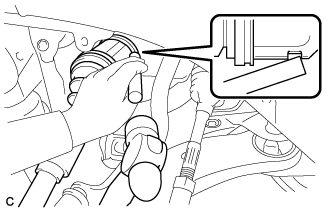 |
Align the inboard joint splines, and using a brass bar and a hammer, install the front drive shaft assembly LH.
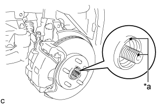 |
Align the matchmarks and install the front drive shaft assembly LH to the front axle hub sub-assembly.
| *a | Matchmark |
| 20. INSTALL FRONT DRIVE SHAFT ASSEMBLY RH |
Coat the spline of the front drive inboard joint assembly with ATF WS.
Coat the lip of the front transaxle case oil seal with MP grease.
Install a new bearing bracket hole snap ring to the front drive shaft assembly RH.
Install the front drive shaft assembly RH.
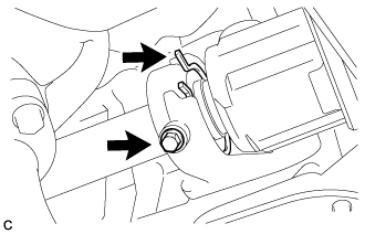 |
Install the bearing bracket hole snap ring and a new bolt.
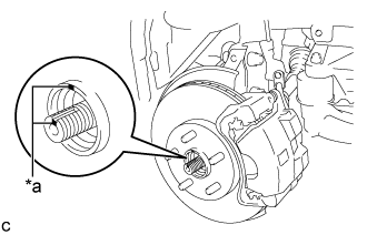 |
Align the matchmarks and install the front drive shaft assembly RH to the front axle hub sub-assembly.
| *a | Matchmark |
| 21. CONNECT FRONT LOWER NO. 1 SUSPENSION ARM SUB-ASSEMBLY LH |
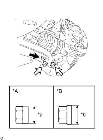 |
Connect the front lower No. 1 suspension arm sub-assembly to the front lower ball joint assembly with the bolt and 2 nuts.
| *A | for TMC, TMMR Made |
| *B | for TMMK Made |
| *a | 20 mm (0.787 in.) |
| *b | 22 mm (0.866 in.) |
| Bolt |
 | Nut |
| 22. CONNECT FRONT LOWER NO. 1 SUSPENSION ARM SUB-ASSEMBLY RH |
| 23. CONNECT TIE ROD ASSEMBLY LH |
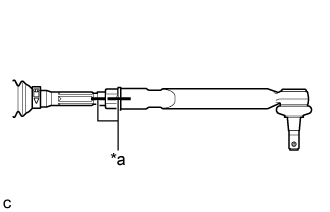 |
Install the lock nut and tie rod assembly LH to the steering rack end sub-assembly until the matchmarks are aligned.
| *a | Matchmark |
| 24. CONNECT TIE ROD ASSEMBLY RH |
| 25. INSTALL FRONT SPEED SENSOR LH |
Install the front speed sensor and front flexible hose to the front shock absorber assembly with the bolt and clamp.
Install the front speed sensor to the steering knuckle with the bolt.
| 26. INSTALL FRONT SPEED SENSOR RH |
| 27. INSTALL FRONT STABILIZER LINK ASSEMBLY LH |
for Steel Type:
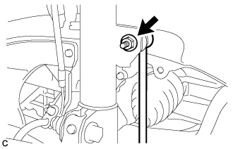 |
Install the front stabilizer link assembly to the front shock absorber assembly with the nut.
for Aluminum Type:
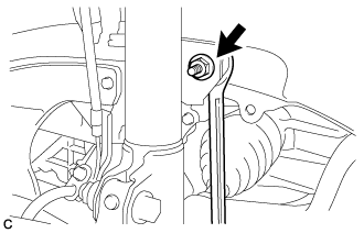 |
Install the front stabilizer link assembly to the front shock absorber assembly with the nut.
| 28. INSTALL FRONT STABILIZER LINK ASSEMBLY RH |
| 29. INSTALL FRONT AXLE SHAFT NUT LH |
Clean the threaded parts on the front drive shaft assembly and a new axle shaft nut using a non-residue solvent.
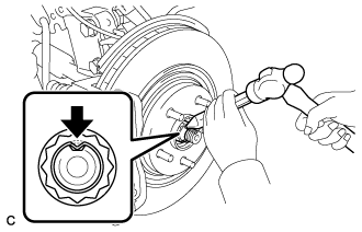 |
Using a socket wrench (30 mm), install the front axle shaft nut.
Using a chisel and a hammer, stake the front axle shaft nut.
| 30. INSTALL FRONT AXLE SHAFT NUT RH |
| 31. CONNECT STEERING INTERMEDIATE SHAFT ASSEMBLY |
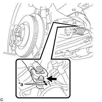 |
Align the matchmarks and install the steering intermediate shaft to the steering link assembly.
| *a | Matchmark |
Install the bolt.
| 32. INSTALL FRONT EXHAUST PIPE ASSEMBLY |
Install 3 new gaskets to the front exhaust pipe assembly.
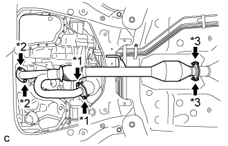 |
Install the front exhaust pipe assembly with the 4 bolts and 4 nuts.
| *1 | Bolt |
| *2 | Nut |
| *3 | Bolt and Nut |
Install the No. 1 exhaust pipe support bracket with the 2 bolts (for Rear Side).
Connect the 2 heated oxygen sensor connectors.
Install the 2 wire harnesses to the clamp.
| 33. INSTALL NO. 1 EXHAUST PIPE SUPPORT BRACKET |
Install the No. 1 exhaust pipe support bracket with the 2 nuts (for Front Side).
| 34. CONNECT NO. 1 COOLER REFRIGERANT SUCTION HOSE |
Remove the vinyl tape from the No. 1 cooler refrigerant suction hose and compressor and magnetic clutch.
Sufficiently apply compressor oil to a new O-ring and the fitting surface of the compressor and magnetic clutch.
Install the O-ring to the No. 1 cooler refrigerant suction hose.
Connect the No. 1 cooler refrigerant suction hose to the compressor and magnetic clutch with the bolt.
| 35. CONNECT NO. 1 COOLER REFRIGERANT DISCHARGE HOSE |
Remove the vinyl tape from the No. 1 cooler refrigerant discharge hose and compressor and magnetic clutch.
Sufficiently apply compressor oil to a new O-ring and the fitting surface of the compressor and magnetic clutch.
Install the O-ring to the No. 1 cooler refrigerant discharge hose.
Connect the No. 1 cooler refrigerant discharge hose to the compressor and magnetic clutch with the bolt.
Engage the 2 clamps and connect the 3 connectors.
| 36. CONNECT FUEL MAIN TUBE |
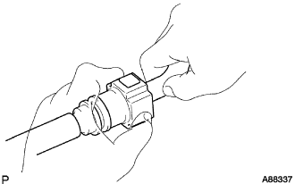 |
Push in the fuel tube connector to the fuel main tube until the fuel tube connector makes a "click" sound.
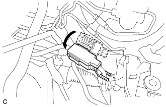 |
Install the No. 1 fuel pipe clamp.
| 37. CONNECT TRANSMISSION CONTROL CABLE ASSEMBLY |
Connect the transmission control cable assembly to the transmission control cable bracket with a new clip.
Connect the transmission control cable assembly to the transmission control shaft lever with the nut.
| 38. INSTALL AIR CLEANER BRACKET |
Install the air cleaner bracket to the battery carrier with the bolt.
Connect the 2 wire clamps.
| 39. CONNECT ENGINE WIRE |
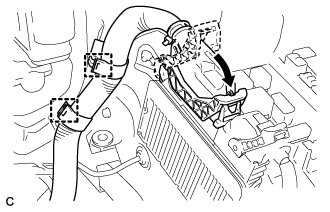 |
Connect the 2 wire clamps.
Connect the connector to the ECM with the lock lever.
Connect the engine wire to the engine room relay block.
Connect the 4 connectors.
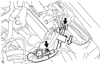 |
Connect the engine wire to the engine room relay block.
Connect the wire clamp and install the 2 nuts.
Install the No. 1 relay block cover.
| 40. INSTALL STARTER ASSEMBLY |
Install the starter assembly with the 2 bolts.
Connect the starter connector.
Install the terminal nut and cover the nut with the cap.
| 41. CONNECT OUTLET HEATER WATER HOSE |
Connect the outlet heater water hose with the hose clip.
| 42. CONNECT INLET HEATER WATER HOSE |
Connect the inlet heater water hose with the hose clip.
| 43. CONNECT INLET NO. 1 OIL COOLER HOSE |
Connect the inlet No. 1 oil cooler hose to the automatic transaxle assembly with the hose clip.
| 44. CONNECT OUTLET NO. 1 OIL COOLER HOSE |
Connect the outlet No. 1 oil cooler hose to the automatic transaxle assembly with the hose clip.
| 45. CONNECT NO. 2 RADIATOR HOSE |
Connect the No. 2 radiator hose with the hose clip.
| 46. CONNECT NO. 1 RADIATOR HOSE |
Connect the No. 1 radiator hose with the hose clip.
Install the air fuel ratio sensor wire to the No. 1 radiator hose with the hose clamp.
| 47. CONNECT UNION TO CHECK VALVE HOSE |
Connect the union to check valve hose to the brake booster with the hose clip.
| 48. CONNECT NO. 1 FUEL VAPOR FEED HOSE |
Connect the No. 1 fuel vapor feed hose with the hose clip.
| 49. CONNECT EARTH WIRE |
Install the earth wire with the 2 bolts.
| 50. INSTALL ENGINE MOVING CONTROL ROD |
Temporarily install the engine moving control rod to the engine moving control rod bracket with the bolt.
| 51. INSTALL ENGINE MOVING CONTROL ROD BRACKET |
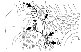 |
When replacing the engine moving control rod.
Install the engine moving control rod bracket with engine moving control rod with the 4 bolts.
Tighten the bolt E.
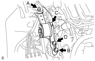 |
When not replacing the engine moving control rod.
Install the engine moving control rod bracket with engine moving control rod with the 4 bolts.
| 52. INSTALL NO. 2 ENGINE MOUNTING STAY RH |
Install the No. 2 engine mounting stay RH with the bolt.
Tighten the 2 nuts.
| 53. INSTALL INTAKE AIR RESONATOR SUB-ASSEMBLY |
Install the intake air resonator sub-assembly with the 2 bolts.
Connect the 2 vacuum hoses and engage the claw.
| 54. INSTALL INLET NO. 1 AIR CLEANER |
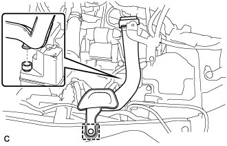 |
Install the inlet No. 1 air cleaner to the intake air resonator sub-assembly.
Engage the pin to the radiator support.
| 55. INSTALL BATTERY |
Install the battery and battery tray.
Install the battery clamp with the bolt and nut.
Connect the positive (+) cable to the positive (+) battery terminal.
| 56. INSTALL AIR CLEANER CASE SUB-ASSEMBLY |
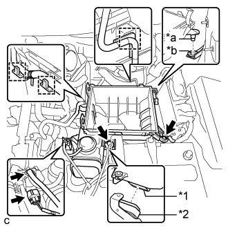 |
Install the air cleaner case sub-assembly to the inlet No. 1 air cleaner.
Insert the projection of the air cleaner case sub-assembly to the hole of the No. 2 air cleaner bracket as shown in the illustration.
| *1 | Air Cleaner Case Sub-assembly |
| *2 | Inlet No. 1 Air Cleaner |
| *a | Projection |
| *b | Hole |
Tighten the 2 bolts.
Connect the wire harness clamp, connector, vacuum hose and No. 1 fuel vapor feed hose.
| 57. INSTALL AIR CLEANER FILTER ELEMENT SUB-ASSEMBLY |
| 58. INSTALL AIR CLEANER CAP SUB-ASSEMBLY |
Connect the air cleaner cap sub-assembly to the throttle with motor body assembly with the hose clamp.
Install the air cleaner cap with hose to the air cleaner case with the 2 clamps.
Connect the wire harness clamp and mass air flow meter connector.
Connect the 3 hoses.
Connect the ventilation hose.
Connect the mass air flow meter connector and wire harness clamp.
| 59. INSTALL INLET NO. 2 AIR CLEANER |
Install the inlet No. 2 air cleaner to the air cleaner case sub-assembly with the 2 bolts.
Connect the 2 wire harness clamps and vacuum hose clamp.
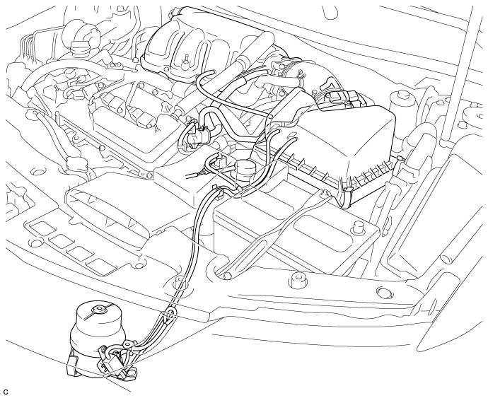
| 60. INSPECT VACUUM HOSES |
Inspect the vacuum hoses.
| 61. CONNECT CABLE TO NEGATIVE BATTERY TERMINAL |
| 62. INSTALL FRONT WHEEL |
| 63. ADD ENGINE OIL |
Add clean engine oil and install the oil filler cap.
 |
| Oil Grade | Oil Viscosity (SAE) |
|
|
|
|
| Item | Standard Condition |
| Drain and refill with oil filter change | 6.1 liters (6.4 US qts, 5.4 lmp. qts) |
| Drain and refill without oil filter change | 5.7 liters (6.0 US qts, 5.0 lmp. qts) |
| Dry fill | 6.8 liters (7.2 US qts, 6.0 lmp. qts) |
| 64. ADD ENGINE COOLANT |
| 65. ADD AUTOMATIC TRANSAXLE FLUID |
| 66. CHARGE AIR CONDITIONING SYSTEM WITH REFRIGERANT |
Perform vacuum purging using a vacuum pump or appropriate equipment.
Charge the air conditioning system with refrigerant.
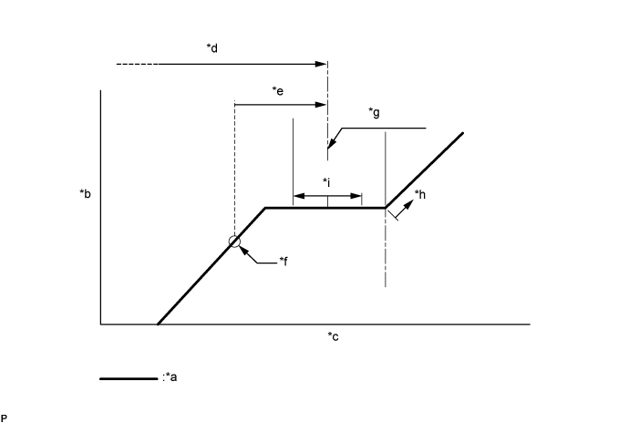
| *a | Sub-cool System | *b | High Pressure |
| *c | Refrigerant Amount | *d | Standard charge amount |
| *e | Charge additional 100 g (3.5 oz) | *f | Point where bubbles disappear |
| *g | Mean value in proper range | *h | Overcharged |
| *i | +/-50 g (+/-1.76 oz) | - | - |
| 67. WARM UP ENGINE |
Keep the A/C switch on for at least 2 minutes to warm up the compressor.
| 68. INSPECT FOR REFRIGERANT LEAK |
After recharging the air conditioning system with refrigerant, check for refrigerant leaks using a halogen leak detector.
Carry out the test under the following conditions:
Remove the front outer cowl top panel sub-assembly .
Remove the radiator side deflector RH .
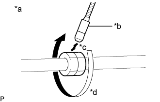 |
How to check for refrigerant leaks in pipe joints:
| *a | Check for leaks |
| *b | Halogen Leak Detector Sensor |
| *c | Distance between Sensor and Joint to be Checked: 10 mm or less |
| *d | Halogen Leak Detector Sensor Moving Speed: 25 to 50 mm/sec. |
Using a halogen leak detector, check for refrigerant leaks at the pipe joints shown in the illustration.
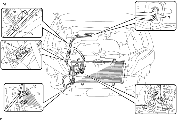
| *a | Area to be Checked | *b | Service Valve (High) |
| *c | Service Valve (Low) | *d | Pipe Joint |
| *e | Air Conditioner Pressure Sensor Joint | *f | Cooler Expansion Valve Joint |
| *g | Condenser Joint (Inlet) | *h | Condenser Joint (Outlet) |
| *i | Compressor Joint (Inlet) | *j | Compressor Joint (Outlet) |
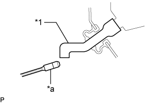 |
Bring the halogen leak detector sensor close to the drain cooler hose with the detector turned off, and then turn the detector on.
| *1 | Drain Cooler Hose |
| *a | Halogen Leak Detector |
Remove the blower motor with fan sub-assembly (Click here).
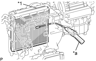 |
Insert the halogen leak detector sensor into the air conditioning unit assembly, bring the sensor close to the No. 1 cooler evaporator sub-assembly and check for refrigerant leaks.
| *1 | No. 1 Cooler Evaporator Sub-assembly |
| *a | Halogen Leak Detector |
Install the blower motor with fan sub-assembly (Click here).
Install the radiator side deflector RH .
Install the front bumper assembly (Click here).
Install the front outer cowl top panel sub-assembly .
Connect the timing light tester probe to the ignition coil wire for No. 1 cylinder.
Check the ignition timing at idle.
Disconnect terminals 13 (TC) and 4 (CG) of the DLC3.
Check the ignition timing at idle.
Confirm that the ignition timing advances immediately when the engine rpm is increased.
Remove the timing light from the engine.
Install the V-bank cover sub-assembly .
| 76. INSPECT ENGINE IDLE SPEED |
Warm up and stop the engine.
When using the intelligent tester:
Check the idle speed.
Connect the intelligent tester to the DLC3.
Start the engine and run it at idle.
Turn the intelligent tester main switch on.
Enter the following menus: Powertrain / Engine / Data List / Engine Speed.
Read the value displayed on the tester.
When not using the intelligent tester:
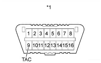 |
Using SST, connect a tachometer probe to terminal 9 (TAC) of the DLC3.
| *1 | DLC3 |
Check the idle speed.
| 77. INSPECT CO/HC |
Start the engine.
Keep the engine speed at 2500 rpm for approximately 180 seconds.
Insert the CO/HC meter testing probe at least 40 cm (1.31 ft.) into the tailpipe during idle.
Immediately check CO/HC concentration during idle and when running at 2500 rpm.
Check the DTCs (Click here).
See the table below for possible causes, then inspect and correct the applicable causes if necessary.
| CO | HC | Problem | Cause |
| Normal | High | Rough idle |
|
| Low | High | Rough idle (Fluctuating HC reading) |
|
| High | High | Rough idle (Black smoke from exhaust) |
|
| 78. CHECK FOR SPEED SENSOR SIGNAL |
| 79. INSPECT SHIFT LEVER POSITION |
When the shift lever is moved from P to R with the engine switch on (IG) and brake pedal depressed, make sure that the shift lever moves smoothly and correctly the position.
Start the engine and make sure that the vehicle moves forward when the shift lever is moved from N to D and moves rearward when the shift lever is moved to R.
| 80. ADJUST SHIFT LEVER POSITION |
Move the shift lever to N.
Remove the console box (Click here).
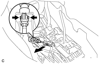 |
Disconnect the end of the transmission control cable assembly from the lower shift lever assembly
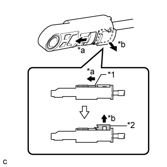 |
Slide the slider of the transmission control cable in the direction indicated by the arrow and pull the lock piece outward.
| *1 | Slider |
| *2 | Lock Piece |
| *a | Slide |
| *b | Pull |
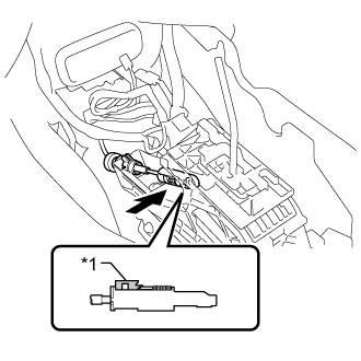 |
Install the end of the transmission control cable to the shift lever assembly.
| *1 | Lock Piece |
Push the lock piece into the adjuster case.
After adjusting the shift lever position, check the operation and function of the shift lever. If there is a problem, adjust the position again.
Install the console box (Click here).
| 81. INSPECT AND ADJUST FRONT WHEEL ALIGNMENT |
| 82. INSTALL V-BANK COVER SUB-ASSEMBLY |
Fit the 3 retainers and install the V-bank cover sub-assembly.
| 83. INSTALL COOL AIR INTAKE DUCT SEAL |
Install the cool air intake duct seal with the 9 clips.
| 84. INSTALL FRONT FENDER APRON SEAL LH |
| 85. INSTALL ENGINE UNDER COVER LH |
| 86. INSTALL FRONT WHEEL OPENING EXTENSION PAD LH |
| 87. INSTALL FRONT FENDER APRON SEAL RH |
| 88. INSTALL FRONT WHEEL OPENING EXTENSION PAD RH |
| 89. INSTALL ENGINE UNDER COVER RH |