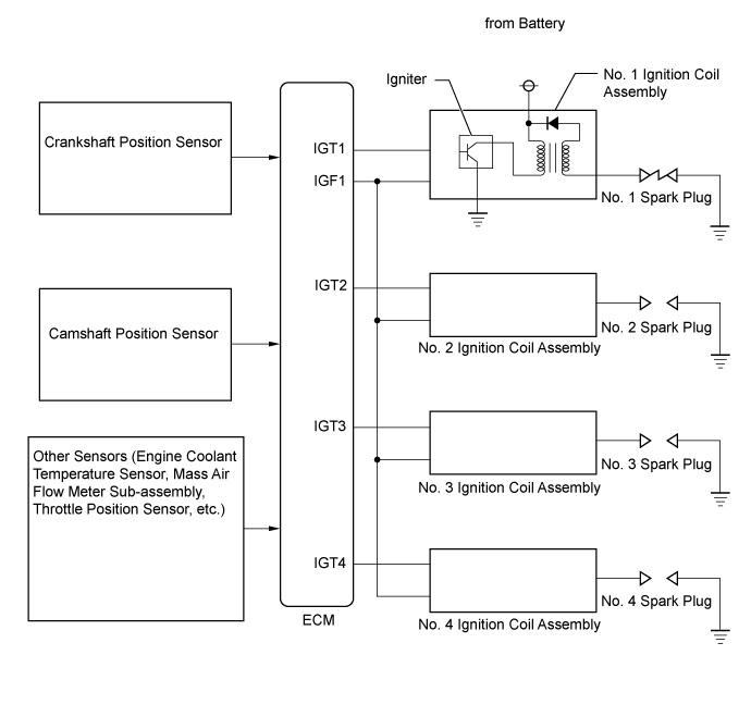
DTC P035113 Ignition Coil "A" Circuit Open |
DTC P035213 Ignition Coil "B" Circuit Open |
DTC P035313 Ignition Coil "C" Circuit Open |
DTC P035413 Ignition Coil "D" Circuit Open |
| DTC No. | DTC Detection Condition | Trouble Area |
| P035113 | No IGF signal to the ECM while the engine is running (1 trip detection logic). |
|
| P035213 | No IGF signal to the ECM while the engine is running (1 trip detection logic). |
|
| P035313 | No IGF signal to the ECM while the engine is running (1 trip detection logic). |
|
| P035413 | No IGF signal to the ECM while the engine is running (1 trip detection logic). |
|
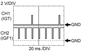
| ECM Terminal Name | CH1: Between IGT (1 to 4) and E1 CH2: Between IGF1 and E1 |
| Tester Range | 2 V/DIV., 20 ms./DIV. |
| Condition | Idling with warm engine |
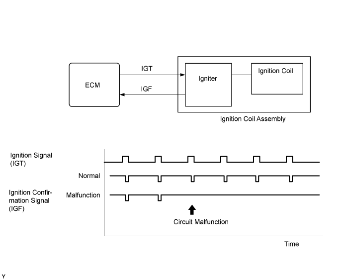
| Required Sensors/Components (Main) | Igniter |
| Required Sensors/Components (Related) | Crankshaft position sensor |
| Frequency of Operation | Continuous |
| GTS Display | Description |
| NORMAL |
|
| ABNORMAL |
|
| INCOMPLETE |
|
| N/A |
|
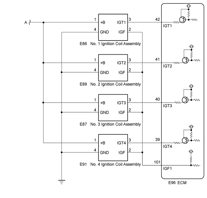
| 1.CHECK WHETHER DTC OUTPUT RECURS (DTC P035113, P035213, P035313 OR P035413) |
Connect the GTS to the DLC3.
Turn the engine switch on (IG).
Turn the GTS on.
Clear the DTCs.
Shuffle the arrangement of the ignition coil assemblies (among No. 1 to No. 4 cylinders).
Perform a simulation test.
Enter the following menus: Powertrain / Engine / Trouble Codes.
Read the DTCs.
| Result | Proceed to |
| Same DTC output | A |
| Different ignition coil DTC output | B |
|
| ||||
| A | |
 |
| 2.CHECK TERMINAL VOLTAGE (POWER SOURCE OF IGNITION COIL ASSEMBLY) |
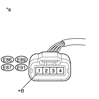 |
Disconnect the ignition coil assembly connector.
| *a | Front view of wire harness connector (to Ignition Coil Assembly) |
Turn the engine switch on (IG).
Measure the voltage according to the value(s) in the table below.
| Tester Connection | Condition | Specified Condition |
| E86-1 (+B) - Body ground | Engine switch on (IG) | 11 to 14 V |
| E89-1 (+B) - Body ground | Engine switch on (IG) | 11 to 14 V |
| E87-1 (+B) - Body ground | Engine switch on (IG) | 11 to 14 V |
| E91-1 (+B) - Body ground | Engine switch on (IG) | 11 to 14 V |
|
| ||||
| OK | |
|
| 3.CHECK HARNESS AND CONNECTOR (IGNITION COIL ASSEMBLY - BODY GROUND) |
Disconnect the ignition coil assembly connector.
Measure the resistance according to the value(s) in the table below.
| Tester Connection | Condition | Specified Condition |
| E86-4 (GND) - Body ground | Always | Below 1 Ω |
| E89-4 (GND) - Body ground | Always | Below 1 Ω |
| E87-4 (GND) - Body ground | Always | Below 1 Ω |
| E91-4 (GND) - Body ground | Always | Below 1 Ω |
|
| ||||
| OK | |
|
| 4.CHECK HARNESS AND CONNECTOR (IGNITION COIL ASSEMBLY - ECM) |
Disconnect the ignition coil assembly connector.
Disconnect the ECM connector.
Measure the resistance according to the value(s) in the table below.
| Tester Connection | Condition | Specified Condition |
| E86-2 (IGF) - E96-101 (IGF1) | Always | Below 1 Ω |
| E89-2 (IGF) - E96-101 (IGF1) | Always | Below 1 Ω |
| E87-2 (IGF) - E96-101 (IGF1) | Always | Below 1 Ω |
| E91-2 (IGF) - E96-101 (IGF1) | Always | Below 1 Ω |
| E86-3 (IGT1) - E96-42 (IGT1) | Always | Below 1 Ω |
| E89-3 (IGT2) - E96-41 (IGT2) | Always | Below 1 Ω |
| E87-3 (IGT3) - E96-40 (IGT3) | Always | Below 1 Ω |
| E91-3 (IGT4) - E96-39 (IGT4) | Always | Below 1 Ω |
| E86-2 (IGF) or E96-101 (IGF1) - Body ground and other terminals | Always | 10 kΩ or higher |
| E89-2 (IGF) or E96-101 (IGF1) - Body ground and other terminals | Always | 10 kΩ or higher |
| E87-2 (IGF) or E96-101 (IGF1) - Body ground and other terminals | Always | 10 kΩ or higher |
| E91-2 (IGF) or E96-101 (IGF1) - Body ground and other terminals | Always | 10 kΩ or higher |
| E86-3 (IGT1) or E96-42 (IGT1) - Body ground and other terminals | Always | 10 kΩ or higher |
| E89-3 (IGT2) or E96-41 (IGT2) - Body ground and other terminals | Always | 10 kΩ or higher |
| E87-3 (IGT3) or E96-40 (IGT3) - Body ground and other terminals | Always | 10 kΩ or higher |
| E91-3 (IGT4) or E96-39 (IGT4) - Body ground and other terminals | Always | 10 kΩ or higher |
|
| ||||
| OK | ||
 | ||
| ||
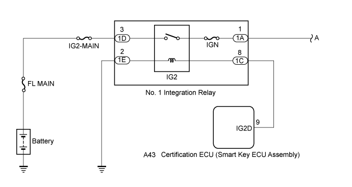
| 5.CHECK HARNESS AND CONNECTOR (NO. 1 INTEGRATION RELAY - IGNITION COIL ASSEMBLY) |
Disconnect the ignition coil assembly connector.
Disconnect the No. 1 integration relay connector.
Measure the resistance according to the value(s) in the table below.
| Tester Connection | Condition | Specified Condition |
| 1A-1 - E86-1 (+B) | Always | Below 1 Ω |
| 1A-1 - E89-1 (+B) | Always | Below 1 Ω |
| 1A-1 - E87-1 (+B) | Always | Below 1 Ω |
| 1A-1 - E91-1 (+B) | Always | Below 1 Ω |
| 1A-1 or E86-1 (+B) - Body ground and other terminals | Always | 10 kΩ or higher |
| 1A-1 or E89-1 (+B) - Body ground and other terminals | Always | 10 kΩ or higher |
| 1A-1 or E87-1 (+B) - Body ground and other terminals | Always | 10 kΩ or higher |
| 1A-1 or E91-1 (+B) - Body ground and other terminals | Always | 10 kΩ or higher |
|
| ||||
| OK | ||
| ||
| ||

