Home › Engine / Hybrid System › N04C-VQ (ENGINE CONTROL) › ECD SYSTEM
RM2850E _51 Engine / Hybrid System _073138 N04C-VQ ENGINE CONTROL _0355854 ECD SYSTEM C

N04C-VQ ENGINE CONTROL  ECD SYSTEM  P0201  Injector Circuit / Open - (Cylinder 1)  P0202  Injector Circuit / Open - (Cylinder 2)  P0203  Injector Circuit / Open - (Cylinder 3)  P0204  Injector Circuit / Open - (Cylinder 4)  P062D  No. 1 Fuel Injector Driver Circuit Performance  


DESCRIPTION

The injector driver assembly has been adopted to drive the injector assembly at high speeds. The injector driver assembly has realized high-speed driving under high fuel pressure conditions through the use of a DC/DC converter sub-assembly that provides a high-voltage, quick-charging system.

The ECM constantly monitors the injector driver assembly and stops the engine if an abnormal condition is detected.

DTC No. DTC Detection Condition Trouble Area
P0201 Open or short in No. 1 injector circuit occurs a certain number of times (1 trip detection logic).
·

Open or short in injector driver assembly circuit

·

No. 1 injector assembly

·

Injector driver assembly

·

ECM


P0202 Open or short in No. 2 injector circuit occurs a certain number of times (1 trip detection logic).
·

Open or short in injector driver assembly circuit

·

No. 2 injector assembly

·

Injector driver assembly

·

ECM


P0203 Open or short in No. 3 injector circuit occurs a certain number of times (1 trip detection logic).
·

Open or short in injector driver assembly circuit

·

No. 3 injector assembly

·

Injector driver assembly

·

ECM


P0204 Open or short in No. 4 injector circuit occurs a certain number of times (1 trip detection logic).
·

Open or short in injector driver assembly circuit

·

No. 4 injector assembly

·

Injector driver assembly

·

ECM


P062D Inconsistency in the injection waveforms between the injector driver and ECM while the engine is running a certain number of times (1 trip detection logic).
·

Open or short in injector driver assembly circuit

·

Injector assembly

·

Injector driver assembly

·

ECM


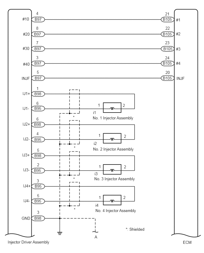
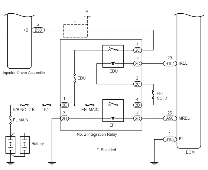
WIRING DIAGRAM

A398535E01
0.792,0.583 1.198,0.781 0.406,0.198 10 false #10 0.813,1.115 1.219,1.313 0.406,0.198 10 false #20 0.802,1.615 1.208,1.813 0.406,0.198 10 false #30 0.813,2.167 1.219,2.365 0.406,0.198 10 false #40 0.76,2.667 1.167,2.865 0.406,0.198 10 false INJF 0.792,3.198 1.198,3.396 0.406,0.198 10 false IJ1+ 0.792,3.719 1.198,3.917 0.406,0.198 10 false IJ1- 0.792,4.271 1.198,4.469 0.406,0.198 10 false IJ2+ 0.813,4.792 1.219,4.99 0.406,0.198 10 false IJ2- 0.781,5.354 1.188,5.552 0.406,0.198 10 false IJ3+ 0.813,5.875 1.219,6.073 0.406,0.198 10 false IJ3- 0.813,6.438 1.219,6.635 0.406,0.198 10 false IJ4+ 0.823,6.958 1.229,7.156 0.406,0.198 10 false IJ4- 0.76,7.573 1.167,7.771 0.406,0.198 10 false GND 0.271,8.406 2.031,8.656 1.76,0.25 10 false Injector Driver Assembly 1.271,0.385 1.552,0.573 0.281,0.188 10 false 4 1.219,0.594 1.615,0.781 0.396,0.188 10 false B97 1.271,0.906 1.521,1.115 0.25,0.208 10 false 8 1.198,1.115 1.594,1.302 0.396,0.188 10 false B97 1.208,1.625 1.604,1.813 0.396,0.188 10 false B97 1.208,2.135 1.604,2.323 0.396,0.188 10 false B97 1.208,3.208 1.625,3.385 0.417,0.177 10 false B98 1.219,2.656 1.615,2.844 0.396,0.188 10 false B97 1.198,4.281 1.615,4.458 0.417,0.177 10 false B98 1.208,3.719 1.625,3.896 0.417,0.177 10 false B95 1.208,4.813 1.625,4.99 0.417,0.177 10 false B95 1.208,5.375 1.625,5.552 0.417,0.177 10 false B98 1.198,5.896 1.615,6.073 0.417,0.177 10 false B95 1.219,6.448 1.635,6.625 0.417,0.177 10 false B95 1.208,6.969 1.625,7.146 0.417,0.177 10 false B95 1.208,7.573 1.625,7.75 0.417,0.177 10 false B98 1.271,1.417 1.521,1.625 0.25,0.208 10 false 7 1.271,1.938 1.521,2.146 0.25,0.208 10 false 3 1.292,2.448 1.542,2.656 0.25,0.208 10 false 5 1.281,3.021 1.531,3.229 0.25,0.208 10 false 1 1.281,3.542 1.531,3.75 0.25,0.208 10 false 6 1.281,4.094 1.531,4.302 0.25,0.208 10 false 6 1.302,5.188 1.552,5.396 0.25,0.208 10 false 5 1.281,4.604 1.531,4.813 0.25,0.208 10 false 4 1.302,5.698 1.552,5.906 0.25,0.208 10 false 2 1.292,6.26 1.542,6.469 0.25,0.208 10 false 3 1.302,6.781 1.552,6.99 0.25,0.208 10 false 5 1.302,7.365 1.552,7.573 0.25,0.208 10 false 3 2.563,4.031 2.813,4.24 0.25,0.208 10 false * 2.594,5.104 2.844,5.313 0.25,0.208 10 false * 2.573,6.198 2.823,6.406 0.25,0.208 10 false * 2.594,7.271 2.844,7.479 0.25,0.208 10 false * 3.323,8.229 3.688,8.438 0.365,0.208 10 false A 4.417,7.958 5.333,8.156 0.917,0.198 10 false *: Shielded 6.427,8.417 7.01,8.615 0.583,0.198 10 false ECM 3.438,3.604 3.688,3.813 0.25,0.208 10 false 1 3.458,4.667 3.708,4.875 0.25,0.208 10 false 1 3.469,5.76 3.719,5.969 0.25,0.208 10 false 1 3.469,6.844 3.719,7.052 0.25,0.208 10 false 1 4.313,3.615 4.563,3.823 0.25,0.208 10 false 2 4.354,4.698 4.604,4.906 0.25,0.208 10 false 2 4.354,5.771 4.604,5.979 0.25,0.208 10 false 2 4.333,6.844 4.583,7.052 0.25,0.208 10 false 2 3.271,3.865 3.573,4.073 0.302,0.208 10 false i1 3.26,4.052 5.031,4.25 1.771,0.198 10 false No. 1 Injector Assembly 3.271,5.146 5.042,5.344 1.771,0.198 10 false No. 2 Injector Assembly 3.292,4.948 3.594,5.156 0.302,0.208 10 false i2 3.313,6.188 5.083,6.385 1.771,0.198 10 false No. 3 Injector Assembly 3.323,6.01 3.625,6.219 0.302,0.208 10 false i3 3.354,7.302 5.125,7.5 1.771,0.198 10 false No. 4 Injector Assembly 3.354,7.115 3.656,7.323 0.302,0.208 10 false i4 5.802,0.406 6.135,0.594 0.333,0.188 10 false 21 5.813,0.906 6.146,1.094 0.333,0.188 10 false 22 5.802,1.417 6.135,1.604 0.333,0.188 10 false 23 5.802,1.948 6.135,2.135 0.333,0.188 10 false 24 5.813,2.458 6.146,2.646 0.333,0.188 10 false 20 5.719,0.594 6.229,0.771 0.51,0.177 10 false B105 5.719,1.115 6.229,1.292 0.51,0.177 10 false B105 5.74,1.625 6.25,1.802 0.51,0.177 10 false B105 5.719,2.135 6.229,2.313 0.51,0.177 10 false B105 5.719,2.656 6.229,2.833 0.51,0.177 10 false B105 6.198,2.667 6.604,2.865 0.406,0.198 10 false INJF 6.188,0.615 6.594,0.813 0.406,0.198 10 false #1 6.188,1.104 6.594,1.302 0.406,0.198 10 false #2 6.188,1.635 6.594,1.833 0.406,0.198 10 false #3 6.188,2.135 6.594,2.333 0.406,0.198 10 false #4

A398537E07
0.802,0.948 1.073,1.115 0.271,0.167 10 false +B 1.198,0.948 1.5,1.125 0.302,0.177 10 false B98 0.094,2.406 1.667,2.615 1.573,0.208 10 false Injector Driver Assembly 0.438,3.677 1.281,3.865 0.844,0.188 10 false R/B NO. 2-B 1.51,3.677 1.792,3.865 0.281,0.188 10 false P/I 0.448,4.031 1.052,4.26 0.604,0.229 10 false FL MAIN 2.802,3.677 3.438,3.875 0.635,0.198 10 false EFI-MAIN 2.667,2.594 3.052,2.792 0.385,0.198 10 false EDU 3.771,2.354 4.156,2.552 0.385,0.198 10 false EDU 2.948,0.313 3.125,0.49 0.177,0.177 10 false A 2.552,0.677 2.729,0.854 0.177,0.177 10 false * 4.656,1.635 4.948,1.823 0.292,0.188 10 false 2C 4.656,2.094 4.948,2.281 0.292,0.188 10 false 2C 4.646,2.802 4.938,2.99 0.292,0.188 10 false 2C 4.646,3.521 4.938,3.708 0.292,0.188 10 false 2D 4.656,3.979 4.948,4.167 0.292,0.188 10 false 2D 2.135,3.521 2.427,3.708 0.292,0.188 10 false 2E 2.135,3.979 2.396,4.156 0.26,0.177 10 false 2D 5.698,2.094 6.083,2.271 0.385,0.177 10 false B104 5.729,3.969 6.031,4.146 0.302,0.177 10 false A56 5.698,4.698 6.115,4.875 0.417,0.177 10 false B102 3.771,4.208 4.156,4.406 0.385,0.198 10 false EFI 3.344,5.052 4.177,5.25 0.833,0.198 10 false *: Shielded 6.406,5.135 6.792,5.333 0.385,0.198 10 false ECM 1.281,0.75 1.542,0.917 0.26,0.167 10 false 2 2.177,3.302 2.302,3.49 0.125,0.188 10 false 1 2.177,3.781 2.302,3.969 0.125,0.188 10 false 3 4.698,1.427 4.823,1.615 0.125,0.188 10 false 4 4.698,1.885 4.823,2.073 0.125,0.188 10 false 3 4.688,2.594 4.813,2.781 0.125,0.188 10 false 2 4.688,3.323 4.813,3.51 0.125,0.188 10 false 4 4.698,3.771 4.823,3.958 0.125,0.188 10 false 2 5.396,3.125 5.854,3.469 0.458,0.344 10 false EFI NO. 2 5.771,1.896 6,2.073 0.229,0.177 10 false 20 6.156,2.083 6.542,2.281 0.385,0.198 10 false IREL 6.156,3.969 6.604,4.156 0.448,0.188 10 false MREL 5.771,3.792 6,3.969 0.229,0.177 10 false 25 5.813,4.49 5.969,4.677 0.156,0.188 10 false 1 6.167,4.677 6.448,4.854 0.281,0.177 10 false E1 1.083,4.844 1.615,5.042 0.531,0.198 10 false Battery 2.646,4.521 4.563,4.708 1.917,0.188 10 false No. 2 Integration Relay

CAUTION / NOTICE / HINT

NOTICE:
·

Inspect the fuses for circuits related to this system before performing the following inspection procedure.

·

After replacing the ECM, the new ECM needs registration (Click hereEngine / Hybrid System>N04C-VQ (ENGINE CONTROL)>ECD SYSTEM>REGISTRATION) and initialization (Click hereEngine / Hybrid System>N04C-VQ (ENGINE CONTROL)>ECD SYSTEM>INITIALIZATION).

·

After replacing the injector assembly, the ECM needs registration (Click hereEngine / Hybrid System>N04C-VQ (ENGINE CONTROL)>ECD SYSTEM>REGISTRATION).


HINT:

Read freeze frame data using the GTS. The ECM records vehicle and driving condition information as freeze frame data the moment a DTC is stored. When troubleshooting, freeze frame data can be helpful in determining whether the vehicle was moving or stationary, whether the engine was warmed up or not, as well as other data recorded at the time of a malfunction.


PROCEDURE
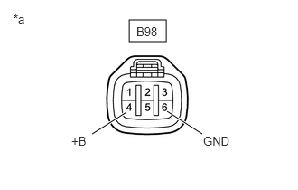
1.CHECK INJECTOR DRIVER ASSEMBLY (+B VOLTAGE)
a.
A256735E04
1.49,0.229 1.917,0.479 0.427,0.25 1.063,1.542 1.458,1.292 true 2.333,1.542 1.927,1.281 true 0.156,0.135 0.469,0.333 0.313,0.198 10 false *a 1.573,0.281 1.927,0.479 0.354,0.198 10 false B98 0.823,1.542 1.135,1.74 0.313,0.198 10 false +B 2.344,1.542 2.854,1.74 0.51,0.198 10 false GND

Disconnect the injector driver assembly connector.


b.

Turn the ignition switch to ON.


c.

Measure the voltage according to the value(s) in the table below.

Standard Voltage:
Tester Connection Switch Condition Specified Condition
B98-2 (+B) - B98-3 (GND) Ignition switch ON 11 to 14 V


Text in Illustration
*a Front view of wire harness connector
(to Injector Driver Assembly)


Result:
Proceed to
OK
NG


OK

2.CHECK INJECTOR DRIVER ASSEMBLY (INJECTOR ASSEMBLY RESISTANCE)

NG

2.CHECK INJECTOR DRIVER ASSEMBLY (INJECTOR ASSEMBLY RESISTANCE)
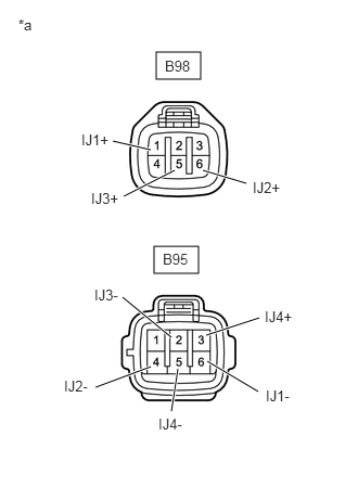
a.
A256736E05
1.5,0.5 1.927,0.76 0.427,0.26 1.479,2.365 1.906,2.625 0.427,0.26 1.083,1.354 1.448,1.438 true 1.188,1.885 1.677,1.635 true 1.948,1.635 2.365,1.76 true 1.646,3.948 1.708,3.542 true 1.177,2.854 1.646,3.24 true 0.917,3.719 1.448,3.521 true 2.479,3.76 1.99,3.469 true 2.49,3.052 1.979,3.219 true 0.177,0.156 0.49,0.354 0.313,0.198 10 false *a 1.583,0.552 1.99,0.75 0.406,0.198 10 false B98 1.563,2.406 1.969,2.604 0.406,0.198 10 false B95 0.781,1.26 1.229,1.458 0.448,0.198 10 false IJ1+ 0.875,1.823 1.323,2.021 0.448,0.198 10 false IJ3+ 2.427,1.719 2.875,1.917 0.448,0.198 10 false IJ2+ 2.542,2.958 2.99,3.156 0.448,0.198 10 false IJ4+ 2.552,3.719 3,3.917 0.448,0.198 10 false IJ1- 1.521,3.99 1.969,4.188 0.448,0.198 10 false IJ4- 0.615,3.625 1.063,3.823 0.448,0.198 10 false IJ2- 0.906,2.75 1.354,2.948 0.448,0.198 10 false IJ3-

Disconnect the injector driver assembly connectors.


b.

Measure the resistance according to the value(s) in the table below.

Standard Resistance:
Tester Connection Condition Specified Condition
B98-1 (IJ1+) - B95-6 (IJ1-) 20°C (68°F) 0.85 to 1.05 Ω
B98-6 (IJ2+) - B95-4 (IJ2-) 20°C (68°F) 0.85 to 1.05 Ω
B98-5 (IJ3+) - B95-2 (IJ3-) 20°C (68°F) 0.85 to 1.05 Ω
B95-3 (IJ4+) - B95-5 (IJ4-) 20°C (68°F) 0.85 to 1.05 Ω


Text in Illustration
*a Front view of wire harness connector
(to Injector Driver Assembly)


Result:
Proceed to
OK
NG


OK

3.CHECK HARNESS AND CONNECTOR (INJECTOR DRIVER ASSEMBLY - ECM)

NG

5.INSPECT INJECTOR ASSEMBLY
3.CHECK HARNESS AND CONNECTOR (INJECTOR DRIVER ASSEMBLY - ECM)
a.

Disconnect the injector driver assembly connector.


b.

Disconnect the ECM connector.


c.

Measure the resistance according to the value(s) in the table below.

Standard Resistance:
Tester Connection Condition Specified Condition
B97-4 (#10) - B105-21 (#1) Always Below 1 Ω
B97-8 (#20) - B105-22 (#2) Always Below 1 Ω
B97-7 (#30) - B105-23 (#3) Always Below 1 Ω
B97-3 (#40) - B105-24 (#4) Always Below 1 Ω
B97-5 (INJF) - B105-20 (INJF) Always Below 1 Ω
B97-4 (#10) or B105-21 (#1) - Body ground Always 10 kΩ or higher
B97-8 (#20) or B105-22 (#2) - Body ground Always 10 kΩ or higher
B97-7 (#30) or B105-23 (#3) - Body ground Always 10 kΩ or higher
B97-3 (#40) or B105-24 (#4) - Body ground Always 10 kΩ or higher
B97-5 (INJF) or B105-20 (INJF) - Body ground Always 10 kΩ or higher


Result:
Proceed to
OK
NG


OK

4.INSPECT ECM (OUTPUT VOLTAGE)

NG

REPAIR OR REPLACE HARNESS OR CONNECTOR (INJECTOR DRIVER ASSEMBLY - ECM)

4.INSPECT ECM (OUTPUT VOLTAGE)
a.

While idling the engine, check the waveform of the ECM connectors using an oscilloscope.
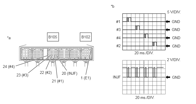
A428875E05
1.729,1.198 2.146,1.51 0.417,0.313 2.927,1.198 3.344,1.51 0.417,0.313 0.573,2.417 1.76,2.031 true 1.031,2.677 1.854,2.021 true 1.677,2.542 1.906,2.021 true 2.094,2.865 2,2.021 true 2.438,2.583 2.052,2.021 true 3.135,2.74 3.323,1.854 true 0.104,2.354 0.583,2.583 0.479,0.229 10 false 24 (#4) 0.26,1.302 0.74,1.531 0.479,0.229 10 false *a 1.458,2.573 1.938,2.802 0.479,0.229 10 false 22 (#2) 1.896,2.885 2.375,3.115 0.479,0.229 10 false 21 (#1) 2.26,2.604 2.906,2.833 0.646,0.229 10 false 20 (INJF) 2.948,2.771 3.427,3 0.479,0.229 10 false 1 (E1) 4.052,0.146 4.531,0.375 0.479,0.229 10 false *b 0.604,2.667 1.083,2.896 0.479,0.229 10 false 23 (#3) 4.917,1.854 5.938,2.115 1.021,0.26 10 false 20 ms./DIV. 6.104,2.104 7.104,2.385 1,0.281 10 false 2 V/DIV. 6.115,0.354 7,0.531 0.885,0.177 10 false 5 V/DIV. 4.125,2.74 4.604,2.969 0.479,0.229 10 false INJF 4.25,0.708 4.729,0.938 0.479,0.229 10 false #1 4.26,1 4.74,1.229 0.479,0.229 10 false #3 4.26,1.302 4.74,1.531 0.479,0.229 10 false #4 4.26,1.594 4.74,1.823 0.479,0.229 10 false #2 6.281,0.708 6.76,0.938 0.479,0.229 10 false GND 6.281,1 6.76,1.229 0.479,0.229 10 false GND 6.292,1.302 6.771,1.531 0.479,0.229 10 false GND 6.292,1.604 6.771,1.833 0.479,0.229 10 false GND 6.292,2.75 6.771,2.979 0.479,0.229 10 false GND 1.771,1.271 2.385,1.469 0.615,0.198 10 false B105 2.979,1.271 3.594,1.469 0.615,0.198 10 false B102 4.948,3.49 5.969,3.75 1.021,0.26 10 false 20 ms./DIV.

Text in Illustration
*a Component with harness connected
(ECM)
*b Signal Waveform

Standard:
Tester Connection Condition Specified Condition
B105-21 (#1) - B102-1 (E1) Idling with warm engine Correct waveform appears as shown
B105-22 (#2) - B102-1 (E1) Idling with warm engine Correct waveform appears as shown
B105-23 (#3) - B102-1 (E1) Idling with warm engine Correct waveform appears as shown
B105-24 (#4) - B102-1 (E1) Idling with warm engine Correct waveform appears as shown
B105-20 (INJF) - B102-1 (E1) Idling with warm engine Correct waveform appears as shown


Result:
Result Proceed to
#1 to #4 is normal, INJF is abnormal A
#1 to #4 is abnormal, INJF is normal B
#1 to #4 and INJF are normal B


A

REPLACE INJECTOR DRIVER ASSEMBLY

B

5.INSPECT INJECTOR ASSEMBLY
a.

Inspect the injector assembly (Click hereEngine / Hybrid System>N04C-VQ (FUEL)>FUEL INJECTOR>INSPECTION).


Result:
Proceed to
OK
NG


OK

REPAIR OR REPLACE HARNESS OR CONNECTOR (INJECTOR DRIVER ASSEMBLY - INJECTOR ASSEMBLY)

NG