N04C-VQ ENGINE CONTROL ECD SYSTEM U1122 Lost Communication with EGR Valve
DESCRIPTION
The CAN (Controller Area Network) is a serial data communication system for real time application. It is a multiplex communication system designed for on-vehicle use that provides a superior communication speed of 500 kbps and a capability to detect malfunctions. Through the combination of the CANH and CANL bus lines, the CAN is able to maintain communication based on differential voltage.
- HINT:
- ·
Malfunctions in the CAN bus (communication line) can be checked from the DLC3. (Except when the sub bus line of the DLC3 is open.)
·Diagnostic codes (DTCs) related to CAN communication can be checked by using the GTS.
·The DLC3 is connected to the CAN communication line, but the CAN communication line cannot detect malfunctions in the DLC3 sub bus line.
| DTC No. | DTC Detection Condition | Trouble Area |
|---|---|---|
| U1122 | Both of the following conditions are met:
(a) Ignition switch ON (b) No communication between ECM and EGR valve assembly for more than 1 seconds |
·
Open or short in EGR valve assembly circuit ·
EGR valve assembly ·
CAN communication system ·
ECM |
WIRING DIAGRAM
Refer to DTC P1458 (Click hereEngine / Hybrid System>N04C-VQ (ENGINE CONTROL)>ECD SYSTEM>P1458).
CAUTION / NOTICE / HINT
- NOTICE:
- ·
After replacing the ECM, the new ECM needs registration (Click hereEngine / Hybrid System>N04C-VQ (ENGINE CONTROL)>ECD SYSTEM>REGISTRATION) and initialization (Click hereEngine / Hybrid System>N04C-VQ (ENGINE CONTROL)>ECD SYSTEM>INITIALIZATION).
·Inspect the fuses for circuits related to this system before performing the following inspection procedure.
PROCEDURE
Connect the GTS to the DLC3.
Turn the ignition switch to ON.
Turn the GTS on.
Clear the DTCs (Click hereEngine / Hybrid System>N04C-VQ (ENGINE CONTROL)>ECD SYSTEM>DTC CHECK / CLEAR).
Turn the ignition switch off.
Turn the ignition switch to ON.
Turn the GTS on.
Enter the following menus: Powertrain / Engine and ECT / Trouble Codes.
Read the DTCs.
- Result:
Result Proceed to DTC U1122 is output A DTC is not output B
A
B
Click hereEngine / Hybrid System>N04C-VQ (ENGINE CONTROL)>ECD SYSTEM>CHECK FOR INTERMITTENT PROBLEMS
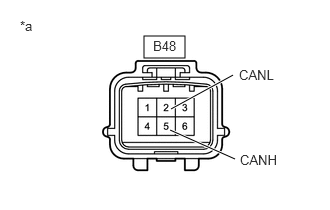
Disconnect the EGR valve connector.
Measure the resistance according to the value(s) in the table below.
- Standard Resistance:
Tester Connection Switch Condition Specified Condition B48-5 (CANH) - B48-2 (CANL) Ignition switch off 54 to 69 Ω
| *a | Front view of wire harness connector
(to EGR Valve Assembly) |
- Result:
Proceed to OK NG
OK
NG
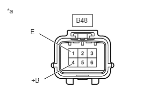
Disconnect the EGR valve connector.
Turn the ignition switch to ON.
Measure the voltage according to the value(s) in the table below.
- Standard Voltage:
Tester Connection Switch Condition Specified Condition B48-4 (+B) - B48-1 (E) Ignition switch ON 11 to 14 V
| *a | Front view of wire harness connector
(to EGR Valve Assembly) |
- Result:
Proceed to OK NG
OK
NG
Disconnect the EGR valve connector.
Measure the resistance according to the value(s) in the table below.
- Standard Resistance:
Tester Connection Condition Specified Condition B48-1 (E) - Body ground Always Below 1 Ω
- Result:
Proceed to OK NG
OK
NG