N04C-VQ ENGINE CONTROL ECD SYSTEM Fuel Injection System
CAUTION / NOTICE / HINT
- NOTICE:
- ·
After replacing the ECM, the new ECM needs registration (Click hereEngine / Hybrid System>N04C-VQ (ENGINE CONTROL)>ECD SYSTEM>REGISTRATION) and initialization (Click hereEngine / Hybrid System>N04C-VQ (ENGINE CONTROL)>ECD SYSTEM>INITIALIZATION).
·After replacing the suction control valve or the injection or supply pump assembly, the ECM needs initialization (Click hereEngine / Hybrid System>N04C-VQ (ENGINE CONTROL)>ECD SYSTEM>INITIALIZATION).
·After replacing the injector assembly, the ECM needs registration (Click hereEngine / Hybrid System>N04C-VQ (ENGINE CONTROL)>ECD SYSTEM>REGISTRATION).
PROCEDURE
Connect the GTS to the DLC3.
Turn the ignition switch to ON.
Turn the GTS on.
Enter the following menus: Powertrain / Engine and ECT / Data List / Fuel Press and Target Common Rail Pressure.
Confirm the values for "Fuel Press" and "Target Common Rail Pressure" when the engine is started.
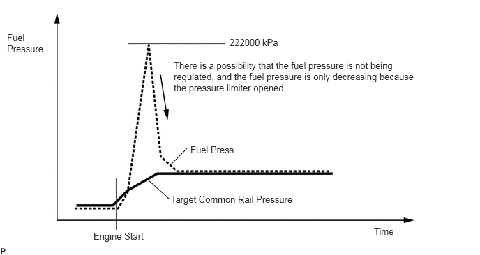
- Result:
Result Proceed to Except below A "Fuel Press" at engine start is more than 222000 kPa B
- HINT:
- ·
Normally, "Fuel Press" does not reach 222000 kPa when the engine is started.
·If "Fuel Press" reaches 222000 kPa when the engine is started, the suction control valve may not be operating (current may not be reaching the suction control valve).
A
B
Connect the GTS to the DLC3.
Turn the ignition switch to ON.
Turn the GTS on.
Enter the following menus: Powertrain / Engine and ECT / Data List / Fuel Press and Target Common Rail Pressure.
Confirm the values for "Fuel Press" and "Target Common Rail Pressure" when the engine is started, and when accelerating and decelerating the vehicle.
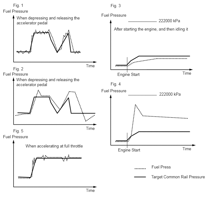
- Result:
Result Proceed to Except below A Fuel Press" is constantly fluctuating and differs from "Target Common Rail Pressure" as shown in figure 1 B "Fuel Press" greatly overshoots "Target Common Rail Pressure" and differs substantially from "Target Common Rail Pressure" as shown in figure 2 Engine does not start, takes a long time to start, or starts but "Fuel Press" is less than "Target Common Rail Pressure" as shown in figure 3 After the engine starts, "Fuel Press" becomes much higher than "Target Common Rail Pressure" and hardly decreases at all as shown in figure 4 "Fuel Press" fluctuates during acceleration or right after accelerating as shown in figure 5 C
- HINT:
- ·
The cases shown in figure 3 and 4 may occur when the learned value for the injection or supply pump assembly is incorrect immediately after the suction control valve, the injection or supply pump assembly, the fuel filter, or the ECM is replaced.
·If "Fuel Press" fluctuates during acceleration as shown in figure 5, there may be air in the fuel system due to an increase in fuel suction vacuum.
A
B
C
- HINT:
-
By performing this Active Test, the engine speed is maintained at 2000 rpm and the common rail assembly internal fuel pressure is raised to the maximum operating pressure. As a result, a fuel leak check can be conducted while retaining the high common rail pressure.
Connect the GTS to the DLC3.
Start the engine.
Turn the GTS on.
Enter the following menus: Powertrain / Engine and ECT / Active Test / Test the Fuel Leak.
Visually check the injection or supply pump assembly, injector assembly and fuel line located between the injection or supply pump assembly and common rail assembly for fuel leaks and fuel pressure leaks. Also, perform the same check on the fuel line between the common rail assembly and the injector assembly.
- HINT:
-
There may be fuel leaks inside the components, such as the injection or supply pump assembly.
- Result:
Result Proceed to No fuel leaks exist A Fuel leaks exist B
A
B
Connect the GTS to the DLC3.
Turn the ignition switch to ON.
Turn the GTS on.
Enter the following menus: Powertrain / Engine and ECT / Data List / Fuel Press and Target Common Rail Pressure.
Confirm the values for "Fuel Press" and "Target Common Rail Pressure" when the accelerator pedal is depressed and then released.
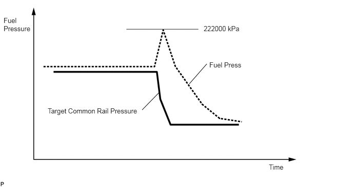
- Result:
Result Proceed to After the accelerator pedal is depressed, "Fuel Press" exceeds 222000 kPa and then decreases. A Except above B
A
B
Check for clogs in the return line for the injector assembly.
- OK:
No clogs in the fuel line
- Result:
Proceed to OK NG
OK
NG
Connect the GTS to the DLC3.
Turn the ignition switch to ON.
Turn the GTS on.
Enter the following menus: Powertrain / Engine and ECT / Data List / Fuel Press and Target Common Rail Pressure.
Confirm the values for "Fuel Press" and "Target Common Rail Pressure" when the engine speed is gradually raised from idle to 3000 rpm.
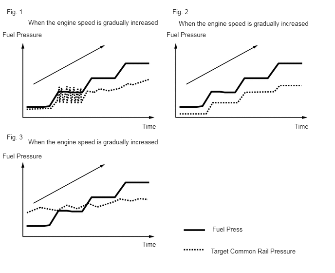
- Result:
Result Proceed to "Fuel Press" becomes unstable in a certain engine speed range and stops following "Target Common Rail Pressure" as shown in figure 1 A "Fuel Press" is continually low and does not follow "Target Common Rail Pressure" as shown in figure 2 "Fuel Press" changes with no relation to "Target Common Rail Pressure" as shown in figure 3 B Except above C
- HINT:
- ·
The cases shown in figure 1 and 2 occur when the amount of fuel supplied by the injection or supply pump assembly is insufficient.
·When the amount of fuel supplied is insufficient, the fuel filter or a fuel pipe being clogged is usually the cause.
A
C
B
Check that there are no clogs in the fuel filter, fuel pipes and fuel suction port in the fuel tank.
Check that the amount of fuel is sufficient.
Inspect the fuel tank, the fuel pipes, the injection or supply pump assembly, the common rail assembly and the injector assemblies for fuel leaks and seepage.
Check if fuel waxing has occurred due to low temperatures.
- HINT:
-
Once fuel waxing occurs, the engine needs to be run for a long time in order for the wax to melt.
Check if the fuel pipes are bent or deformed, preventing fuel from flowing.
- Result:
Proceed to OK NG
OK
NG
Disconnect the ECM connector.
Disconnect the fuel pressure sensor connector.
Measure the resistance according to the value(s) in the table below.
- Standard Resistance:
Tester Connection Condition Specified Condition B105-16 (PCR1) - m1-2 (PCR1) Always Below 1 Ω B104-13 (VC) - m1-1 (VC1) Always Below 1 Ω B104-14 (E2) - m1-3 (E1) Always Below 1 Ω B105-2 (PCR2) - m1-5 (PCR2) Always Below 1 Ω B105-13 (VC2) - m1-6 (VC2) Always Below 1 Ω B105-14 (E21) - m1-4 (E2) Always Below 1 Ω B105-16 (PCR1) or m1-2 (PCR1) - Body ground Always 10 kΩ or higher B104-13 (VC) or m1-1 (VC1) - Body ground Always 10 kΩ or higher B105-2 (PCR2) or m1-5 (PCR2) - Body ground Always 10 kΩ or higher B105-13 (VC2) or m1-6 (VC2) - Body ground Always 10 kΩ or higher B104-14 (E2) or m1-3 (E1) - Other terminals Always 10 kΩ or higher B105-14 (E21) or m1-4 (E2) - Other terminals Always 10 kΩ or higher
- Result:
Proceed to OK NG
OK
NG
- OK:
Fuel does not return from the fuel line of the pressure limiter.
- Result:
Proceed to OK NG
OK
NG
Disconnect the suction control valve connector.
Disconnect the ECM connector.
Measure the resistance according to the value(s) in the table below.
- Standard Resistance:
Tester Connection Condition Specified Condition B103-23 (PCV+) - B52-1 (SCV+) Always Below 1 Ω B103-12 (PCV-) - B52-2 (SCV-) Always Below 1 Ω B103-23 (PCV+) or B52-1 (SCV+) - Body ground Always 10 kΩ or higher B103-12 (PCV-) or B52-2 (SCV-) - Body ground Always 10 kΩ or higher
- Result:
Proceed to OK NG
OK
NG
Perform fuel supply pump initialization (Click hereEngine / Hybrid System>N04C-VQ (ENGINE CONTROL)>ECD SYSTEM>INITIALIZATION).
- Result:
Proceed to NEXT
NEXT
Connect the GTS to the DLC3.
Turn the ignition switch to ON.
Turn the GTS on.
Enter the following menus: Powertrain / Engine and ECT / Data List / Fuel Press and Target Common Rail Pressure.
Perform procedures 1, 2, 4 and 6 and check if the problem symptom disappears.
- Result:
Result Proceed to Problem symptom does not disappear A Problem symptom disappears B
- HINT:
- ·
If the problem symptom disappears, a fuel line may be clogged.
·After checking for clogs in the fuel lines and performing repairs, perform fuel supply pump initialization (Click hereEngine / Hybrid System>N04C-VQ (ENGINE CONTROL)>ECD SYSTEM>INITIALIZATION).
A
B