N04C-VQ EMISSION CONTROL EGR COOLER INSTALLATION
PROCEDURE

 17505G
1.INSTALL NO. 1 EXHAUST PIPE HEAT INSULATOR SUB-ASSEMBLY
Install the No. 1 exhaust pipe heat insulator sub-assembly and 3 bolts.
- Torque:
29 N*m (291 kgf*cm, 21 ft.*lbf)
25608
2.INSTALL EGR COOLER SUB-ASSEMBLY
Connect the No. 1 water by-pass hose and No. 2 water by-pass hose.
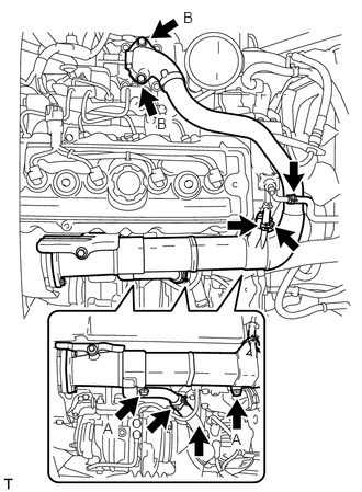
Connect the water by-pass hose and reserve tank hose.
Install new gasket and the EGR cooler sub-assembly with 4 bolts.
- Torque:
- for bolt A:
69 N*m (700 kgf*cm, 51 ft.*lbf)
- for bolt B:
55 N*m (561 kgf*cm, 41 ft.*lbf)
Temporarily install the EGR pipe connector to the EGR cooler sub-assembly and exhaust manifold with the 2 new gaskets, 3 spacers, 3 nuts and 2 bolts.
- NOTICE:
-
Tighten the nuts until they contact the EGR cooler sub-assembly.
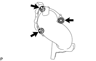
Tighten the 3 nuts.
- Torque:
69 N*m (700 kgf*cm, 51 ft.*lbf)
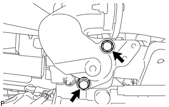
Tighten the 2 bolts.
- Torque:
69 N*m (700 kgf*cm, 51 ft.*lbf)
17505H
3.INSTALL NO. 2 EXHAUST PIPE HEAT INSULATOR SUB-ASSEMBLY
Install the 2 bolts and the No. 2 exhaust pipe heat insulator sub-assembly.
- Torque:
29 N*m (291 kgf*cm, 21 ft.*lbf)
17271
4.INSTALL NO. 4 EXHAUST PIPE HEAT INSULATOR SUB-ASSEMBLY
Install the 3 bolts and the No. 4 exhaust pipe heat insulator sub-assembly.
- Torque:
29 N*m (291 kgf*cm, 21 ft.*lbf)
17271
5.INSTALL NO. 3 EXHAUST PIPE HEAT INSULATOR SUB-ASSEMBLY
Install the 4 bolts and the No. 3 exhaust pipe heat insulator sub-assembly.
- Torque:
29 N*m (291 kgf*cm, 21 ft.*lbf)
17410
6.INSTALL FRONT EXHAUST PIPE ASSEMBLY
11409
7.INSTALL ENGINE OIL LEVEL DIPSTICK GUIDE
Install a new O-ring to the engine oil level dipstick guide.
Install the engine oil level dipstick guide with the bolt.
- Torque:
29 N*m (291 kgf*cm, 21 ft.*lbf)
Connect the 2 wire harness clamps.
44360
8.INSTALL VANE PUMP OIL RESERVOIR ASSEMBLY
44379A
9.INSTALL NO. 2 OIL RESERVOIR BRACKET
53712C
10.INSTALL FRONT FENDER APRON LH
16206
11.INSTALL WATER BY-PASS PIPE SUB-ASSEMBLY
Install the water by-pass pipe sub-assembly with the 5 bolts.
- Torque:
29 N*m (291 kgf*cm, 21 ft.*lbf)
Connect the 2 water by-pass hoses.
12.ADD ENGINE COOLANT
13.INSPECT FOR COOLANT LEAK
14.INSPECT FOR EXHAUST GAS LEAK
58701A
15.INSTALL FRONT ENGINE SERVICE COVER PANEL SUB-ASSEMBLY
33506F
16.INSTALL FLOOR SHIFT CONTROL SHIFT LEVER RETAINER SUB-ASSEMBLY
58123A
17.INSTALL SHIFT AND SELECT LEVER SUPPORT WITH BOOTS
58420
18.INSTALL NO. 2 ENGINE SERVICE HOLE COVER ASSEMBLY
58734B
19.INSTALL REAR ENGINE SERVICE COVER WEATHERSTRIP
58410
20.INSTALL ENGINE SERVICE HOLE COVER
58521D
21.INSTALL ENGINE SERVICE HOLE COVER MAT