14B ENGINE MECHANICAL CYLINDER HEAD CYLINDER HEAD INSTALLATION
PROCEDURE

 1.CHECK PISTON PROTRUSION AND SELECT CYLINDER HEAD GASKET (14B)
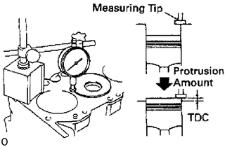
Check piston protrusions for each cylinder
Clean the cylinder block with solvent.
Set the piston of the cylinder to be measured to slightly before TDC.
Place a dial indicator on the cylinder block, and set the dial indicator at 0 mm (0 in.).
- HINT:
- ·
Use a dial indicator measuring tip as shown in the illustration.
·Make sure that the measuring tip is square to the cylinder block gasket surface and piston head when taking the measurements.
Find where the piston head protrudes most by slowly turning the crankshaft clockwise and counterclockwise.
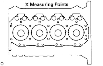
Measure each cylinder at 2 places as shown in the illustration, making a total of 8 measurements.
For the piston protrusion value of each cylinder, use the average of the 2 measurements of each cylinder.
- Protrusion:
0.535 - 0.985 mm (0.0211 - 0.0388 in.)
When removing piston and connecting rod assembly:
If the protrusion is not as specified, remove the piston and connecting rod assembly and reinstall it.
Click hereEngine / Hybrid System>14B (ENGINE MECHANICAL)>CYLINDER BLOCK>CYLINDER BLOCK DISASSEMBLY
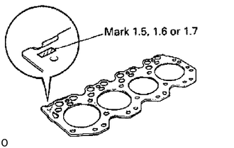
Select new cylinder head gasket
- HINT:
-
There are 3 sizes of new cylinder head gaskets, marked "1.5", "1.6" or "1.7" accordingly.
- New installed cylinder head gasket thickness:
Mark "1.5" 1.47 - 1.53 mm (0.0579 - 0.0602 in.) Mark "1.6" 1.57 - 1.63 mm (0.0618 - 0.0642 in.) Mark "1.7" 1.67 - 1.73 mm (0.0657 - 0.0681 in.)
Select the largest piston protrusion value from the measurements made, then select a new appropriate gasket according to the table below.
| Piston protrusion mm (in.) | Gasket size |
|---|---|
| 0.535 - 0.785 (0.0211 - 0.0309) | Use "1.5" |
| 0.785 - 0.885 (0.0309 - 0.0348) | Use "1.6" |
| 0.885 - 0.985 (0.0348 - 0.0388) | Use "1.7" |
11101
2.INSTALL CYLINDER HEAD ASSEMBLY
Place cylinder head on cylinder block
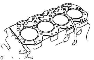
Place a new cylinder head gasket in position on the cylinder block.
- NOTICE:
-
Be careful of the installation direction.
Place the cylinder head in position on the cylinder head gasket.
Install cylinder head bolts
- HINT:
- ·
The cylinder head bolts are tightened in 3 progressive steps (steps [*1], [*2] and [*3]).
·If any bolts is broken or deformed, replace it.
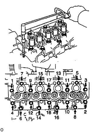
Apply a light coat of engine oil on the threads and under the heads of the cylinder head bolts.
Install and uniformly tighten the 18 cylinder head bolts, in several passes, in the sequence shown.[*1]
- Torque:
49 N*m (500 kgf*cm, 36 ft.*lbf)
If any one of the cylinder head bolts does not meet the torque specification, replace the cylinder head bolt.
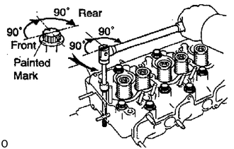
Mark the front of the cylinder head bolt with paint.
Retighten the cylinder head bolts 90° in the numerical order shown.[*2]
Retighten cylinder head bolts by an additional 90°.[*3]
Check that the painted mark is now facing rearward.
3.INSTALL PUSH RODS
13901
4.INSTALL VALVE ROCKER SHAFT ASSEMBLY
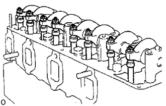
Place the rocker shaft assembly on the cylinder head.
Align the rocker arm adjusting screws with the heads of the push rods.
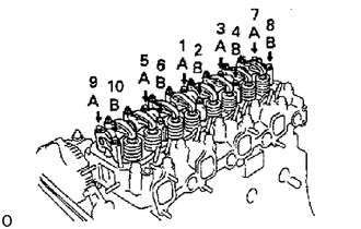
Install and uniformly tighten the 10 bolts, in several passes, in the sequence shown.
- Torque:
25 N*m (255 kgf*cm, 18 ft.*lbf)
- HINT:
-
Each bolt length is indicated in the illustration.
- Bolt length:
A 63 mm (2.48 in.)
B 53 mm (2.08 in.)
5.ADJUST VALVE CLEARANCE
Click hereEngine / Hybrid System>14B (ENGINE MECHANICAL)>VALVE CLEARANCE>INSPECTION AND ADJUSTMENT
Reference
- Valve cleerance (Cold):
Intake 0.25 mm (0.010 in.)
Exhaust 0.40 mm (0.016 in.)
11201
6.INSTALL CYLINDER HEAD COVER
Install the gasket to the cylinder head cover.
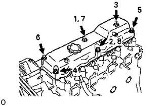
Install and uniformly tighten the cylinder head cover with the 6 cushions, 4 bolts and 2 nuts, in several passes, in the sequence shown.
- Torque:
10.5 N*m (107 kgf*cm, 8 ft.*lbf)
17141
7.INSTALL EXHAUST MANIFOLD
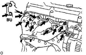
Install a new gasket, the exhaust manifold and No.2 heat insulator (BU) with the 8 bolts and new 2 nuts.
Uniformly tighten the bolts and nuts in several passes.
- Torque:
47.5 N*m (484 kgf*cm, 35 ft.*lbf)
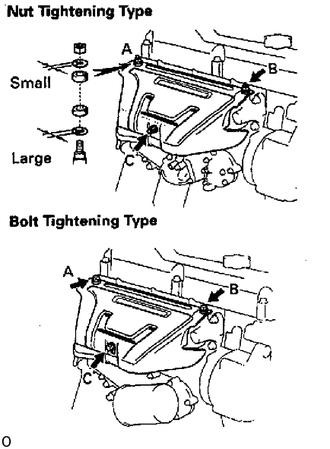
Nut tightening type:
Install the 3 plate washers and 3 spacers to the stud bolts on the exhaust manifold.
- HINT:
-
Install the plate washers with the large inside diameter.
Nut tightening type:
Install the heat insulator with the 3 plate washers and 3 nuts.
- HINT:
-
Install the plate washers with the small inside diameter.
Bolt tightening type:
Place the heat insulator on the exhaust manifold.
Install and tighten the 3 nuts or bolts with these order.
First, temporarily tighten nuts or bolts A and B. Then fully tighten nuts or bolts C, A and B.
- Torque:
18.5 N*m (189 kgf*cm, 14 ft.*lbf)
16381
8.INSTALL DRIVE BELT ADJUSTING BAR
- Torque:
44 N*m (449 kgf*cm, 32 ft.*lbf)
9.ADJUST DRIVE BELT(S)
- Torque:
- Adjusting bolt:
18.5 N*m (189 kgf*cm, 14 ft.*lbf)
- Pivot bolt:
37.5 N*m (382 kgf*cm, 28 ft.*lbf)
16333
10.INSTALL WATER OUTLET ASSEMBLY
Install a new gasket to the intake manifold.
Connect the water bypass hose to the water pump.
Install the water outlet assembly with the 2 nuts.
- Torque:
18.5 N*m (189 kgf*cm, 14 ft.*lbf)
11.INSTALL REAR ENGINE HANGER
- Torque:
37 N*m (380 kgf*cm, 27 ft.*lbf)
17111
12.INSTALL INTAKE MANIFOLD
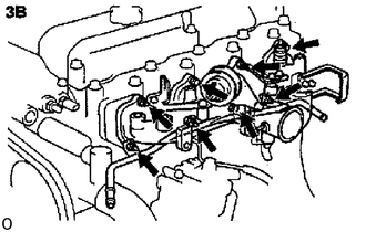
3B:
Install a new gasket, the intake manifold, venturi assembly, oil dipstick guide support (BU), and PS return pipe with the 3 bolts and 5 nuts. Uniformly tighten the bolts and nuts in several passes.
- Torque:
18.5 N*m (189 kgf*cm, 14 ft.*lbf)
14B:
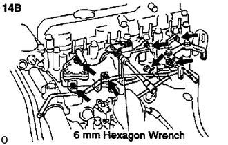
Install a new gasket, the intake manifold, oil dipstick guide support (BU), and PS return pipe with the 2 bolts and 5 nuts. Uniformly tighten the bolts and nuts in several passes.
- Torque:
18.5 N*m (189 kgf*cm, 14 ft.*lbf)
14B:
Using a 6 mm hexagon wrench. install the bolt.
- Torque:
18.5 N*m (189 kgf*cm, 14 ft.*lbf)
14B:
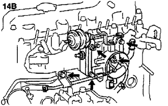
Install the venturi, intake heater assembly and idle-up actuator with the 2 bolts and 2 nuts (w/o ACSD) or nut (w/ ACSD).
- Torque:
21 N*m (214 kgf*cm, 15 ft.*lbf)
w/ ACSD for 14B:
Install the holding bolt and nut the water bypass pipe to the intake manifold and venturi.
21905C
13.INSTALL ACCELERATOR CONNECTING ROD
25706
14.INSTALL VACUUM PIPE (BB)
Install the vacuum pipe with the 3 bolts.
- Torque:
- Timing gear cover side:
21 N*m (214 kgf*cm, 15 ft.*lbf)
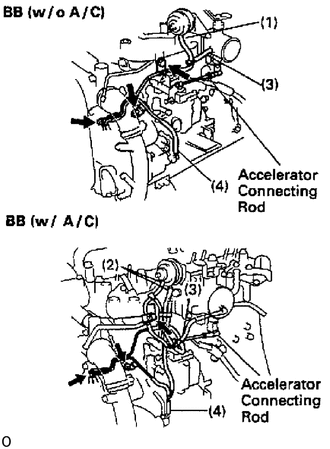
Connect these vacuum hoses:
w/o A/C:
Vacuum hose to idle-up actuator
w/ A/C:
2 vacuum hoses to the idle-up actuator
Vacuum hose to venturi or intake shutter
Vacuum hose to vacuum pipe
15.INSTALL OIL DIPSTICK GUIDE AND OIL DIPSTICK (BB)
16.INSTALL GLOW PLUGS (3B)
Install the 4 glow plugs.
- Torque:
12.5 N*m (127 kgf*cm, 9 ft.*lbf)
Install the glow plug connector with the 4 nuts.
Install the 4 screw grommets.
23600
17.INSTALL INJECTION NOZZLES
12261
18.INSTALL PCV HOSE
19. FILL WITH ENGINE COOLANT
20. START ENGINE AND CHECK FOR LEAKS
21.RECHECK ENGINE COOLANT LEVEL
22.READJUST VALVE CLEARANCE
23.READJUST DRIVE BELT(S)