AIR CONDITIONING REAR HEATER UNIT INSTALLATION
CAUTION / NOTICE / HINT
- HINT:
- ·
Use the same procedure for LHD and RHD vehicles.
·The procedure listed below is for the RHD vehicles.
PROCEDURE

 87120
1.INSTALL REAR HEATER ASSEMBLY
for Front Side:
Install the rear heater assembly with the 3 bolts.
- Torque:
Torque: 7.0 N*m (71 kgf*cm, 62 in.*lbf)
for Rear Side:
Install the rear heater assembly with the 2 bolts and nut.
- Torque:
Torque: 7.0 N*m (71 kgf*cm, 62 in.*lbf)
87209
2.CONNECT WATER HOSE SUB-ASSEMBLY (for Front Side, RHD)
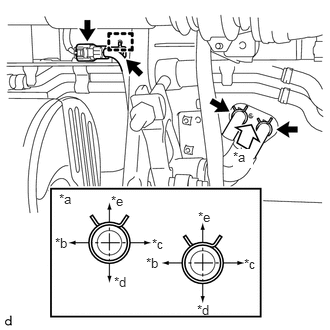
Type A:
Connect the 2 water hose sub-assemblies with the 2 clamps as shown in the illustration.
| *a | View A |
| *b | Front of Vehicle |
| *c | Rear of Vehicle |
| *d | Right of Vehicle |
| *e | Left of Vehicle |
Connect the connector.
Attach the guide.
Install the bolt.
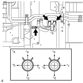
Type B:
Connect the 2 water hose sub-assemblies with the 2 clamps as shown in the illustration.
| *a | View A |
| *b | Front of Vehicle |
| *c | Rear of Vehicle |
| *d | Right of Vehicle |
| *e | Left of Vehicle |
Connect the connector.
Attach the guide.
87209
3.CONNECT WATER HOSE SUB-ASSEMBLY (for Front Side, LHD)
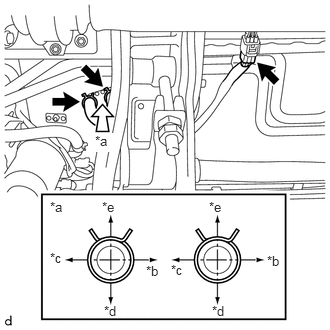
Connect the 2 water hose sub-assemblies with the 2 clamps as shown in the illustration.
| *a | View A |
| *b | Front of Vehicle |
| *c | Rear of Vehicle |
| *d | Right of Vehicle |
| *e | Left of Vehicle |
Connect the connector.
Attach the guide.
87209
4.CONNECT WATER HOSE SUB-ASSEMBLY (for Rear Side, RHD)
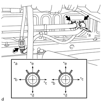
Connect the 2 water hose sub-assemblies with the 2 clamps as shown in the illustration.
| *a | View A |
| *b | Front of Vehicle |
| *c | Rear of Vehicle |
| *d | Right of Vehicle |
| *e | Left of Vehicle |
Connect the connector.
87209
5.CONNECT WATER HOSE SUB-ASSEMBLY (for Rear Side, LHD)
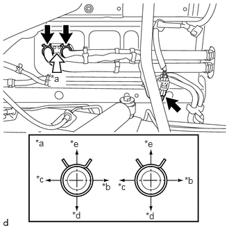
Connect the 2 water hose sub-assemblies with the 2 clamps as shown in the illustration.
| *a | View A |
| *b | Front of Vehicle |
| *c | Rear of Vehicle |
| *d | Right of Vehicle |
| *e | Left of Vehicle |
Connect the connector.
6.ADD ENGINE COOLANT (for 14B)
7.ADD ENGINE COOLANT (for 1HZ)
8.ADD ENGINE COOLANT (for 2TR-FE)
9.ADD ENGINE COOLANT (for N04C-UH, N04C-VL, N04C-VQ)
for N04C-UH
Click hereEngine / Hybrid System>N04C-UH (COOLING)>COOLANT>REPLACEMENT
for N04C-VL
Click hereEngine / Hybrid System>N04C-VL (COOLING)>COOLANT>REPLACEMENT
for N04C-VQ
Click hereEngine / Hybrid System>N04C-VQ (COOLING)>COOLANT>REPLACEMENT
10.INSPECT FOR ENGINE COOLANT LEAK (for 14B)
11.INSPECT FOR ENGINE COOLANT LEAK (for 1HZ)
12.INSPECT FOR ENGINE COOLANT LEAK (for 2TR-FE)
13.INSPECT FOR ENGINE COOLANT LEAK (for N04C-UH, N04C-VL, N04C-VQ)
for N04C-UH
Click hereEngine / Hybrid System>N04C-UH (COOLING)>COOLANT>REPLACEMENT
for N04C-VL
Click hereEngine / Hybrid System>N04C-VL (COOLING)>COOLANT>REPLACEMENT
for N04C-VQ
Click hereEngine / Hybrid System>N04C-VQ (COOLING)>COOLANT>REPLACEMENT
14.INSTALL REAR SEAT ASSEMBLY LH
for 2-Passenger Seat with Separate Type Seatback
for 2-Passenger Seat with Bench Type Seatback
for Single-Passenger Seat with 3 Point Type Seat Belt
for Single-Passenger Seat without 3 Point Type Seat Belt
15.INSTALL REAR SEAT ASSEMBLY RH
for 2-Passenger Seat with Separate Type Seatback
for 2-Passenger Seat with Bench Type Seatback
for Single-Passenger Seat with 3 Point Type Seat Belt
for Single-Passenger Seat without 3 Point Type Seat Belt