BRAKE SYSTEM (OTHER) BRAKE BOOSTER(for RHD with Brake pedal Load Sensing Switch) INSTALLATION
PROCEDURE

 47264D
1.INSTALL BRAKE MASTER CYLINDER PUSH ROD CLEVIS
Temporarily install the lock nut and brake master cylinder push rod clevis to the brake booster assembly.
- HINT:
-
Tighten the lock nut when adjusting the brake pedal height.
44610
2.INSTALL BRAKE BOOSTER ASSEMBLY
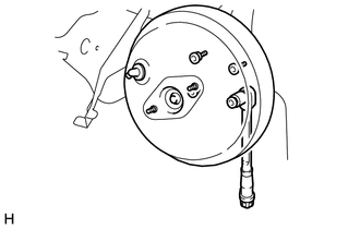
Install the brake booster assembly to the pedal bracket sub-assembly with the 4 nuts.
- Torque:
13 N*m (133 kgf*cm, 10 ft.*lbf)
Install push rod pin (Click hereBrake>BRAKE SYSTEM (OTHER)>BRAKE PEDAL (w/ Brake pedal Load Sensing Switch)>INSTALLATION).
55106D
3.INSTALL PEDAL BRACKET SUB-ASSEMBLY
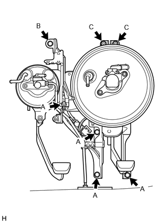
Install the pedal bracket sub-assembly with the 5 bolts and 2 nuts.
- Torque:
- bolt A:
19 N*m (194 kgf*cm, 14 ft.*lbf)
- Torque:
- bolt B:
8.0 N*m (82 kgf*cm, 71 in.*lbf)
- Torque:
- nut C:
20 N*m (199 kgf*cm, 14 ft.*lbf)
Connect the clamps to the pedal bracket sub-assembly.
4.CONNECT VACUUM HOSE ASSEMBLY
Connect the vacuum hose assembly to the brake booster assembly with the clip.
5.CONNECT NO. 1 CLUTCH BOOSTER VACUUM HOSE
6.INSTALL BRAKE TUBE
Temporarily install a new clamp to the brake pedal bracket sub-assembly with the bolt.
Temporarily connect the 2 brake tubes and the master cylinder to tube connector to the tube connector.
Connect the 2 brake tubes and the master cylinder to tube connector to the clamp.
Install the clamp to the brake pedal bracket sub-assembly with the bolt.
- Torque:
7.5 N*m (76 kgf*cm, 66 in.*lbf)
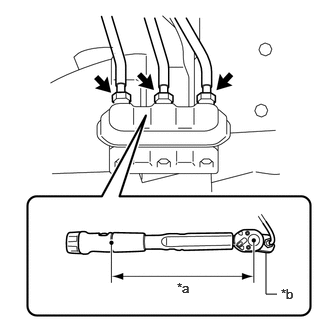
Using a union nut wrench, tighten the 2 brake tubes and the master cylinder to tube connector to the tube connector.
- Torque:
- Specified tightening torque:
24 N*m (245 kgf*cm, 18 ft.*lbf)
- HINT:
- ·
Calculate the torque wrench reading when changing the fulcrum length of the torque wrench (Click hereGeneral>INTRODUCTION>REPAIR INSTRUCTION>PRECAUTION).
·When using a union nut wrench (fulcrum length of 20 mm (0.787 in.)) + torque wrench (fulcrum length of 180 mm (7.09 in.)): 22 N*m (224 kgf*cm, 16 ft.*lbf)
| *a | Torque Wrench Fulcrum Length |
| *b | Union Nut Wrench |
47201
7.INSTALL BRAKE MASTER CYLINDER SUB-ASSEMBLY
55305C
8.INSTALL INSTRUMENT PANEL REINFORCEMENT SUB-ASSEMBLY
Install the instrument panel reinforcement sub-assembly with the 4 bolts.
- Torque:
18 N*m (184 kgf*cm, 13 ft.*lbf)
55330B
9.INSTALL INSTRUMENT PANEL REINFORCEMENT ASSEMBLY
10.INSTALL STEERING COLUMN ASSEMBLY
55301
11.INSTALL INSTRUMENT PANEL SUB-ASSEMBLY