2TR-FE ENGINE MECHANICAL CAMSHAFT INSTALLATION
PROCEDURE

 13050
1.INSTALL CAMSHAFT TIMING GEAR ASSEMBLY
Check that the straight pin is installed on the camshaft.
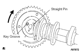
Put the camshaft timing gear and camshaft together with the straight pin and key groove misaligned.
- NOTICE:
-
Do not forcefully push in the camshaft timing gear assembly. This may cause the camshaft straight pin tip to damage the installation surface of the camshaft timing gear assembly.
Turn the camshaft timing gear while pushing it gently against the camshaft. Push more firmly at the position where the pin fits into the groove.
- NOTICE:
-
Do not turn the camshaft timing gear in the retard direction (clockwise).
Check the there is no clearance between the gear and camshaft flange.
Tighten the flange bolt with the camshaft timing gear fixed in place.
- Torque:
78 N*m (795 kgf*cm, 58 ft.*lbf)
Check that the camshaft timing gear can move to the retard angle side (clockwise) and is locked in the most retarded position.
13716
2.INSTALL VALVE STEM CAP
Apply clean engine oil to the valve stem tip, and install the valve stem cap.
- NOTICE:
-
Install the cap onto the same place it was removed from.
13750
3.INSTALL VALVE LASH ADJUSTER ASSEMBLY
- NOTICE:
- ·
Keep the lash adjuster free from dirt and foreign objects.
·Only use clean engine oil.
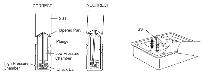
Place the lash adjuster into a container full of engine oil.
Insert SST's tip into the lash adjuster's plunger and use the tip to press down on the check ball inside the plunger.
- SST
- 09276-75010
Squeeze SST and lash adjuster together to move the plunger up and down 5 to 6 times.
Check the movement of the plunger and bleed air.
- OK:
Plunger moves up and down.
- NOTICE:
-
When bleeding high-pressure air from the compression chamber, make sure that the tip of the SST is actually pressing the check ball as shown in the illustration. If the check ball is not pressed, air will not bleed.
After bleeding air, remove SST. Then, try to quickly and firmly press the plunger with a finger.
- OK:
Plunger is very difficult to move.
If the result is not as specified, replace the lash adjuster.
Install the lash adjuster.
- HINT:
-
Repeat the same procedures and install the remaining lash adjusters.
- NOTICE:
-
Install the lash adjuster into the same place it was removed from.
13801
4.INSTALL VALVE ROCKER ARM SUB-ASSEMBLY
Apply clean engine oil to the valve lash adjuster tips and valve stem cap surfaces. Then install the valve rocker arms.
- NOTICE:
-
Install the valve stem cap and valve rocker arm onto the same place they were removed from.
13511
5.INSTALL CAMSHAFTS
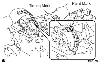
Apply clean engine oil to the camshaft's cam portion and the cylinder head journals.
Install the timing chain onto the camshaft timing gear, with the painted mark of the link aligned with the timing mark on the camshaft timing gear.
Set the camshaft and No. 2 camshaft as shown in the illustration.
- NOTICE:
- ·
Align the paint mark and timing mark before setting the camshaft.
·Before and after setting the camshaft and No. 2 camshaft, check that the rocker arm is firmly set onto the lash adjuster.
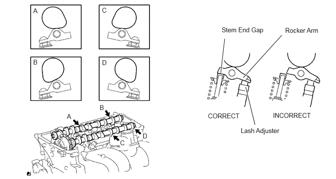
Temporarily install the No. 1 camshaft bearing cap.
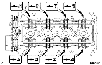
Check the proper location of each camshaft bearing cap and install each one as shown in the illustration.
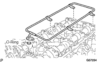
Install a new O-ring onto the No. 1 camshaft bearing cap.
Temporarily install the oil delivery pipe.
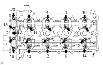
Tighten the 21 bolts and 20 washers in the order shown in the illustration.
- Torque:
- Bolt A:
12 N*m (122 kgf*cm, 9 ft.*lbf)
- except Bolt A:
16 N*m (158 kgf*cm, 11 ft.*lbf)
13523
6.INSTALL CAMSHAFT TIMING GEAR OR SPROCKET
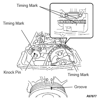
Rotate the camshaft so that the camshaft's timing mark and the No. 2 camshaft knock pin are as shown in the illustration.
Turn the crankshaft pulley, and align its groove with timing mark 0 on the timing chain cover.
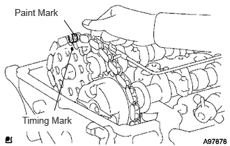
Install the timing chain onto the camshaft timing sprocket, with the paint mark aligned with the timing marks on the camshaft timing sprocket.
Align the No. 2 camshaft knock pin and camshaft timing sprocket's pin hole. Then install the camshaft timing sprocket onto the No. 2 camshaft.
- NOTICE:
-
If the knock pin and pin hole are difficult to align, slightly rotate the No. 2 camshaft to the left and right using the hexagonal part of the camshaft. Then attempt alignment again.
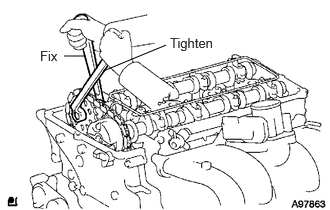
Fix the camshaft with a wrench, and then tighten the sprocket bolt.
- Torque:
78 N*m (795 kgf*cm, 58 ft.*lbf)
Remove the hexagon wrench from the chain tensioner.
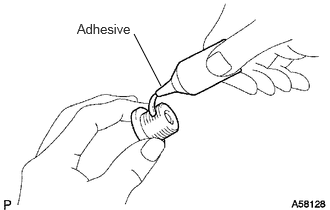
Apply adhesive to 2 or 3 threads of the timing chain cover plug.
- Adhesive:
Toyota Genuine Adhesive 1324, Three Bond 1324 or equivalent
- NOTICE:
-
Remove any oil from the bolt hole.
Using a 10 mm socket hexagon wrench, install the timing gear case plug.
- Torque:
17 N*m (169 kgf*cm, 12 ft.*lbf)
13566B
7.INSTALL TIMING CHAIN GUIDE
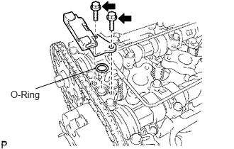
Install a new O-ring onto the camshaft bearing cap.
Install the timing chain guide with the 2 bolts.
- Torque:
10 N*m (102 kgf*cm, 7 ft.*lbf)
11201
8.INSTALL CYLINDER HEAD COVER SUB-ASSEMBLY
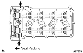
Install the 2 new gaskets onto the cylinder head cover.
Remove any old packing (FIPG) material.
Apply seal packing to 2 locations as shown in the illustration.
- Seal packing:
Toyota Genuine Seal Packing Black, Three Bond 1207B or equivalent
- NOTICE:
- ·
Remove any oil from the contact surface.
·Install the cylinder head cover within 3 minutes of applying the seal packing.
·Do not apply engine oil for at least 2 hours after installing.
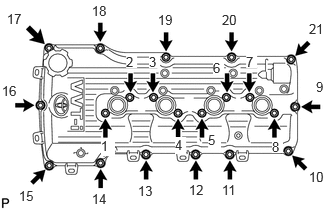
Temporarily install the head cover with the 19 bolts and 2 nuts.
Uniformly tighten the 19 bolts and 2 nuts in the sequence shown in the illustration.
- Torque:
9.0 N*m (92 kgf*cm, 80 in.*lbf)
Connect the wire harness to the 6 clamps.
19500
9.INSTALL IGNITION COIL ASSEMBLY
Install the 4 ignition coils with the 4 bolts.
- Torque:
9.0 N*m (92 kgf*cm, 80 in.*lbf)
17861
10.INSTALL INTAKE AIR CONNECTOR
16361A
11.INSTALL FAN AND GENERATOR V BELT
88310A
12.INSTALL NO. 1 V (COOLER COMPRESSOR TO CRANKSHAFT PULLEY) BELT
51405A
13.INSTALL NO. 1 ENGINE UNDER COVER
14.CONNECT CABLE TO NEGATIVE BATTERY TERMINAL
15.INSPECT FOR ENGINE OIL LEAK
16.INSPECT FOR COOLANT LEAK
17.CHECK IGNITION TIMING
18.CHECK ENGINE IDLING SPEED
19.CHECK CO/HC
58701A
20.INSTALL FRONT ENGINE SERVICE COVER PANEL SUB-ASSEMBLY
33506F
21.INSTALL FLOOR SHIFT CONTROL SHIFT LEVER RETAINER SUB-ASSEMBLY
58123A
22.INSTALL SHIFT AND SELECT LEVER SUPPORT WITH BOOTS
58420
23.INSTALL NO. 2 ENGINE SERVICE HOLE COVER ASSEMBLY
58521D
24.INSTALL ENGINE SERVICE HOLE COVER MAT
58734B
25.INSTALL REAR ENGINE SERVICE COVER WEATHERSTRIP
58410
26.INSTALL ENGINE SERVICE HOLE COVER