A861E AUTOMATIC TRANSMISSION / TRANSAXLE AUTOMATIC TRANSMISSION SYSTEM P0746 Pressure Control Solenoid "A" Performance/Stuck OFF P0776 Pressure Control Solenoid "B" Performance/Stuck OFF P2757 Torque Converter Clutch Pressure Control Solenoid Control Circuit Performance/Stuck OFF
DESCRIPTION
There are 8 oil pressure switches installed inside the valve body. The operation of each solenoid, shift valve, control valve, etc. changes the oil path inside the valve, which causes each oil pressure switch to change between on and off. The No. 1 oil pressure switch operates based on the status of shift solenoid valve SL1 and control valve No. 1. The No. 2 oil pressure switch operates based on the status of shift solenoid valve SL2 and control valve No. 2. The No. 7 oil pressure switch operates based on the status of shift solenoid valve SL3 and control valve No. 3. When there is a malfunction in the TPS1 signal system, TPS2 signal system or TPS7 signal system, or a malfunction in the solenoid or control valve system, the transmission control ECU assembly stores the applicable DTC.
| DTC No. | Detection Item | DTC Detection Condition | Trouble Area | Warning Indicate | Memory |
|---|---|---|---|---|---|
| P0746 | Pressure Control Solenoid "A" Performance/Stuck OFF | 1. Diagnosis Condition 2. Malfunction Status 3. Malfunction Time 4. Other
DTC Detection Condition 1:
1.
Shift lever in D, 4 or 2/L, engine running 2.
During a low pressure command (C1 clutch, C2 clutch, and B1 brake inactivation signals output), the No. 1 oil pressure switch does not turn off 3.
Continues for 0.5 seconds or more, 3 times consecutively 4.
1 trip detection logic DTC Detection Condition 2:
1.
Shift lever in D, 4 or 2/L, engine running 2.
During a high pressure command (C1 clutch, C2 clutch, and B1 brake activation signals output), the No. 1 oil pressure switch does not turn on 3.
0.3 seconds or more 4.
1 trip detection logic |
·
Wire harness or connector (No. 1 oil pressure switch signal circuit) ·
No. 2 transmission wire ·
No. 1 oil pressure switch ·
Transmission control ECU assembly |
O/D OFF Indicator Light: Blinking | DTC stored |
| P0776 | Pressure Control Solenoid "B" Performance/Stuck OFF | 1. Diagnosis Condition 2. Malfunction Status 3. Malfunction Time 4. Other
DTC Detection Condition 1:
1.
Shift lever in D, 4 or 2/L, engine running 2.
During a low pressure command (C3 clutch and B2 brake inactivation signals output), the No. 2 oil pressure switch does not turn off 3.
Continues for 0.5 seconds or more, 3 times consecutively 4.
1 trip detection logic DTC Detection Condition 2:
1.
Shift lever in D, 4 or 2/L, engine running 2.
During a high pressure command (C3 clutch and B2 brake activation signals output), the No. 2 oil pressure switch does not turn on 3.
0.3 seconds or more 4.
1 trip detection logic |
·
Wire harness or connector (No. 2 oil pressure switch signal circuit) ·
No. 2 transmission wire ·
No. 2 oil pressure switch ·
Transmission control ECU assembly |
O/D OFF Indicator Light: Blinking | DTC stored |
| P2757 | Torque Converter Clutch Pressure Control Solenoid Control Circuit Performance/Stuck OFF | 1. Diagnosis Condition 2. Malfunction Status 3. Malfunction Time 4. Other
DTC Detection Condition 1:
1.
Shift lever shifted N to D or N to R while engine running 2.
When shifting from N to D or N to R, the No. 7 oil pressure switch does not turn on 3.
Continues for 0.5 seconds or more, 3 times consecutively 4.
1 trip detection logic DTC Detection Condition 2:
1.
Shift lever in D, 4 or 2/L, engine running 2.
During a low pressure command (C1 clutch and C3 clutch inactivation signals output), The No. 7 oil pressure switch does not turn off 3.
0.5 seconds or more 4.
1 trip detection logic |
·
Wire harness or connector (No. 7 oil pressure switch signal circuit) ·
No. 1 transmission wire ·
No. 7 oil pressure switch ·
Transmission control ECU assembly |
O/D OFF Indicator Light: Blinking | DTC stored |
CONFIRMATION DRIVING PATTERN
- HINT:
-
After the repair, clear the DTCs and perform the following procedure to check that DTCs are not output.
Perform the D Position Shift Test inspection in Road Test.
Click hereDrivetrain>A861E (AUTOMATIC TRANSMISSION / TRANSAXLE)>AUTOMATIC TRANSMISSION SYSTEM>ROAD TEST
Check for DTCs again.
WIRING DIAGRAM
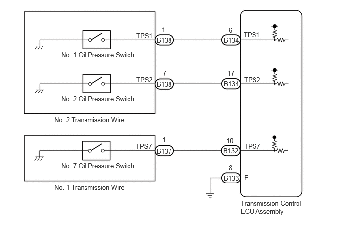
CAUTION / NOTICE / HINT
- NOTICE:
-
Perform initialization when parts related to the automatic transmission are replaced.
-
Click hereDrivetrain>A861E (AUTOMATIC TRANSMISSION / TRANSAXLE)>AUTOMATIC TRANSMISSION SYSTEM>INITIALIZATION
- HINT:
- ·
Refer to Parts Location for the location of each shift solenoid valve and each oil pressure switch.
Click hereDrivetrain>A861E (AUTOMATIC TRANSMISSION / TRANSAXLE)>AUTOMATIC TRANSMISSION SYSTEM>PARTS LOCATION
·Use a new transmission wire if the pin and socket terminals are removed on each oil pressure switch.
PROCEDURE
Connect the GTS to the DLC3.
Turn the ignition switch to ON.
Turn the GTS on.
Enter the following menus: Powertrain / ECT / Trouble Codes.
Read DTCs using the GTS.
- Result:
Result Proceed to DTC P0746, P0776, P2757 are output A DTC P0746, P0776, P2757 and other DTCs are output B
- HINT:
-
If any other codes besides P0746, P0776, P2757 are output, perform troubleshooting for those DTCs first.
A
B
Disconnect the No. 1 transmission wire connector.
Disconnect the No. 2 transmission wire connector.
Disconnect the transmission control ECU assembly connectors.
Measure the resistance according to the value(s) in the table below.
- Standard Resistance:
Tester Connection Condition Specified Condition B138-1 (TPS1) - B134-6 (TPS1) Always Below 1 Ω B138-7 (TPS2) - B134-17 (TPS2) Always Below 1 Ω B137-1 (TPS7) - B132-10 (TPS7) Always Below 1 Ω B138-1 (TPS1) or B134-6 (TPS1) - Body ground Always 10 kΩ or higher B138-7 (TPS2) or B134-17 (TPS2) - Body ground Always 10 kΩ or higher B137-1 (TPS7) or B132-10 (TPS7) - Body ground Always 10 kΩ or higher
- Result:
Proceed to OK NG
OK
NG
Start the engine.
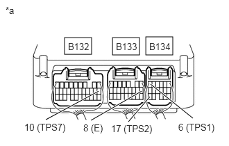
| *a | Component with harness connected
(Transmission Control ECU Assembly) |
Measure the voltage according to the value(s) in the table below.
- Standard Voltage:
Tester Connection Condition Specified Condition B134-1 (TPS1) - B133-8 (E) ·Engine idling speed
·Shift lever in P
·No. 1 oil pressure switch off
11 to 14 V ·Run the vehicle in 2nd gear
·No. 1 oil pressure switch on
Below 1 V B134-17 (TPS2) - B133-8 (E) ·Engine idling speed
·Shift lever in D
·No. 2 oil pressure switch off
11 to 14 V ·Engine idling speed
·Shift lever in R
·No. 2 oil pressure switch on
Below 1 V B132-10 (TPS7) - B133-8 (E) ·Engine idling speed
·Shift lever in P
·No. 7 oil pressure switch off
11 to 14 V ·Engine idling speed
·Shift lever in R
·No. 7 oil pressure switch on
Below 1 V
- Result:
Result Proceed to OK A NG (No. 1 oil pressure switch) B NG (No. 2 oil pressure switch) C NG (No. 7 oil pressure switch) D
A
B
C
D
Remove the No. 2 transmission wire.
Click hereDrivetrain>A861E (AUTOMATIC TRANSMISSION / TRANSAXLE)>TRANSMISSION WIRE>REMOVAL
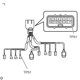
| *1 | No. 2 Transmission Wire |
Measure the resistance according to the value(s) in the table below.
- Standard Resistance:
Tester Connection Condition Specified Condition 1 (TPS1) - TPS1 No. 1 oil pressure switch side Always Below 1 Ω 1 (TPS1) or TPS1 No. 1 oil pressure switch side - Other terminals Always 10 kΩ or higher
- Result:
Proceed to OK NG
OK
Click hereDrivetrain>A861E (AUTOMATIC TRANSMISSION / TRANSAXLE)>SHIFT SOLENOID VALVE>REMOVAL
- HINT:
-
Use a new transmission wire if the pin and socket terminals are removed on each oil pressure switch.
NG
Remove the No. 2 transmission wire.
Click hereDrivetrain>A861E (AUTOMATIC TRANSMISSION / TRANSAXLE)>TRANSMISSION WIRE>REMOVAL
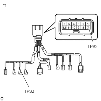
| *1 | No. 2 Transmission Wire |
Measure the resistance according to the value(s) in the table below.
- Standard Resistance:
Tester Connection Condition Specified Condition 7 (TPS2) - TPS2 No. 2 oil pressure switch side Always Below 1 Ω 7 (TPS2) or TPS2 No. 2 oil pressure switch side - Other terminals Always 10 kΩ or higher
- Result:
Proceed to OK NG
OK
Click hereDrivetrain>A861E (AUTOMATIC TRANSMISSION / TRANSAXLE)>SHIFT SOLENOID VALVE>REMOVAL
- HINT:
-
Use a new transmission wire if the pin and socket terminals are removed on each oil pressure switch.
NG
Remove the No. 1 transmission wire.
Click hereDrivetrain>A861E (AUTOMATIC TRANSMISSION / TRANSAXLE)>TRANSMISSION WIRE>REMOVAL
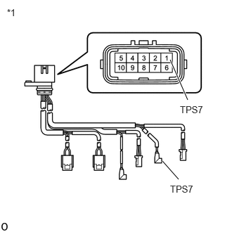
| *1 | No. 1 Transmission Wire |
Measure the resistance according to the value(s) in the table below.
- Standard Resistance:
Tester Connection Condition Specified Condition 1 (TPS7) - TPS7 No. 7 oil pressure switch side Always Below 1 Ω 1 (TPS7) or TPS7 No. 7 oil pressure switch side - Other terminals Always 10 kΩ or higher
- Result:
Proceed to OK NG
OK
Click hereDrivetrain>A861E (AUTOMATIC TRANSMISSION / TRANSAXLE)>SHIFT SOLENOID VALVE>REMOVAL
- HINT:
-
Use a new transmission wire if the pin and socket terminals are removed on each oil pressure switch.
NG