Home › Drivetrain › A861E (AUTOMATIC TRANSMISSION / TRANSAXLE) › AUTOMATIC TRANSMISSION SYSTEM › 2019.08–2021.01
RM2850E _52 Drivetrain _082622 A861E AUTOMATIC TRANSMISSION / TRANSAXLE _0398655 AUTOMATIC TRANSMISSION SYSTEM C

A861E AUTOMATIC TRANSMISSION / TRANSAXLE  AUTOMATIC TRANSMISSION SYSTEM  U0100  Lost Communication With ECM/PCM "A"  


DESCRIPTION

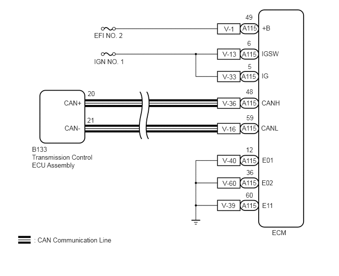
The ECM communicates with the transmission control ECU assembly via the Controller Area Network (CAN).

If there is a problem in communication, the transmission control ECU assembly stores this DTC.

DTC No. Detection Item DTC Detection Condition Trouble Area Warning Indicate Memory
U0100 Lost Communication With ECM/PCM "A" 1. Diagnosis Condition 2. Malfunction Status 3. Malfunction Time 4. Other
1.

Battery voltage 10 V or higher and 1 second or more elapses since recovering from low voltage status

2.

Lost communication between ECM and transmission control ECU assembly

3.

2 seconds or more

4.

1 trip detection logic


·

Wire harness or connector

·

ECM

·

Transmission control ECU assembly

·

CAN communication system


O/D OFF Indicator Light: Blinking DTC stored

CONFIRMATION DRIVING PATTERN

HINT:

After the repair, clear the DTCs and perform the following procedure to check that DTCs are not output.


1.

Turn the ignition switch to ON.


WIRING DIAGRAM

C421144E01
5.542,0.51 5.854,0.708 0.313,0.198 10 false +B 5.531,1.052 6.146,1.25 0.615,0.198 10 false IGSW 5.531,1.521 6.146,1.719 0.615,0.198 10 false IG 5.531,2.094 6.146,2.292 0.615,0.198 10 false CANH 5.521,2.625 6.135,2.823 0.615,0.198 10 false CANL 5.542,3.302 6,3.5 0.458,0.198 10 false E01 5.531,3.781 5.99,3.979 0.458,0.198 10 false E02 5.542,4.26 6,4.458 0.458,0.198 10 false E11 5.188,0.281 5.5,0.479 0.313,0.198 10 false 49 5.125,0.51 5.74,0.708 0.615,0.198 10 false A115 5.115,1.063 5.729,1.26 0.615,0.198 10 false A115 5.104,1.531 5.719,1.729 0.615,0.198 10 false A115 5.115,2.094 5.729,2.292 0.615,0.198 10 false A115 5.115,2.625 5.729,2.823 0.615,0.198 10 false A115 5.115,3.313 5.729,3.51 0.615,0.198 10 false A115 5.115,3.781 5.729,3.979 0.615,0.198 10 false A115 5.115,4.26 5.729,4.458 0.615,0.198 10 false A115 4.688,4.26 5.302,4.458 0.615,0.198 10 false V-39 4.708,3.792 5.323,3.99 0.615,0.198 10 false V-60 4.708,3.313 5.323,3.51 0.615,0.198 10 false V-40 4.698,2.646 5.313,2.844 0.615,0.198 10 false V-16 4.708,2.104 5.323,2.302 0.615,0.198 10 false V-36 4.708,1.542 5.323,1.74 0.615,0.198 10 false V-33 4.708,1.063 5.323,1.26 0.615,0.198 10 false V-13 4.74,0.531 5.354,0.729 0.615,0.198 10 false V-1 5.229,0.833 5.385,1.031 0.156,0.198 10 false 6 5.24,1.323 5.396,1.521 0.156,0.198 10 false 5 5.198,1.854 5.51,2.052 0.313,0.198 10 false 48 5.208,2.406 5.521,2.604 0.313,0.198 10 false 59 5.198,3.083 5.51,3.281 0.313,0.198 10 false 12 5.208,3.563 5.521,3.76 0.313,0.198 10 false 36 5.198,4.042 5.51,4.24 0.313,0.198 10 false 60 1.354,2.094 1.969,2.292 0.615,0.198 10 false CAN+ 1.365,2.625 1.979,2.823 0.615,0.198 10 false CAN- 1.854,1.896 2.167,2.094 0.313,0.198 10 false 20 1.844,2.458 2.156,2.656 0.313,0.198 10 false 21 0.719,4.99 4.385,5.188 3.667,0.198 10 false : CAN Communication Line 1.99,0.667 3.365,0.865 1.375,0.198 10 false EFI NO. 2 1.99,1.219 3.365,1.417 1.375,0.198 10 false IGN NO. 1 0.677,3.24 2.063,3.781 1.385,0.542 10 false Transmission Control ECU Assembly 5.75,4.833 6.208,5.031 0.458,0.198 10 false ECM 0.677,3.073 1.292,3.271 0.615,0.198 10 false B133

CAUTION / NOTICE / HINT

NOTICE:
·

Inspect the fuses for circuits related to this system before performing the following inspection procedure.

·

Perform initialization when parts related to the automatic transmission are replaced.

Click hereDrivetrain>A861E (AUTOMATIC TRANSMISSION / TRANSAXLE)>AUTOMATIC TRANSMISSION SYSTEM>INITIALIZATION


PROCEDURE

1.INSPECT ECM (POWER SOURCE)
a.

Disconnect the ECM connector.


b.

Connect the signal check harness to the ECM and ECM vehicle side harness.


c.

Turn the ignition switch to ON.


d.
A405886C03
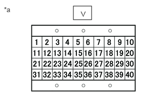
1.51,0.125 1.885,0.406 0.375,0.281 0.083,0.115 0.396,0.313 0.313,0.198 10 false *a 1.667,0.208 1.979,0.406 0.313,0.198 10 false V
*a Signal Check Harness Lead Connector


Measure the voltage according to the value(s) in the table below.

Click hereEngine / Hybrid System>N04C-WA (ENGINE CONTROL)>ECD SYSTEM>TERMINALS OF ECM

Standard Voltage:
Tester Connection Condition Specified Condition
V-1 - Body ground Ignition switch ON 11 to 14 V
V-13 - Body ground Ignition switch ON 11 to 14 V
V-33 - Body ground Ignition switch ON 11 to 14 V


Result:
Proceed to
OK
NG


OK

2.CHECK HARNESS AND CONNECTOR (ECM - BODY GROUND)

NG

2.CHECK HARNESS AND CONNECTOR (ECM - BODY GROUND)
a.

Disconnect the ECM connector.


b.

Connect the signal check harness to the ECM vehicle side harness. (Do not connect harness to the ECM)


c.
A405886C03
1.51,0.125 1.885,0.406 0.375,0.281 0.083,0.115 0.396,0.313 0.313,0.198 10 false *a 1.667,0.208 1.979,0.406 0.313,0.198 10 false V
*a Signal Check Harness Lead Connector


Measure the resistance according to the value(s) in the table below.

Click hereEngine / Hybrid System>N04C-WA (ENGINE CONTROL)>ECD SYSTEM>TERMINALS OF ECM

Standard Resistance:
Tester Connection Condition Specified Condition
V-40 - Body ground Always Below 1 Ω
V-60 - Body ground Always Below 1 Ω
V-39 - Body ground Always Below 1 Ω


Result:
Proceed to
OK
NG


OK

NG

REPAIR OR REPLACE HARNESS OR CONNECTOR