METER / GAUGE / DISPLAY METER / GAUGE SYSTEM B1500 Fuel Sender Open Detected
DESCRIPTION
This DTC is stored when the combination meter assembly detects a fuel sender gauge assembly malfunction via a direct line.
| DTC No. | Detection Item | DTC Detection Condition | Trouble Area | Memory |
|---|---|---|---|---|
| B1500 | Fuel Sender Open Detected | When IG voltage is 9.5 V or more and the following condition is detected:
·
Average input signal of fuel sender gauge assembly is 630 Ω or more 3 times consecutively |
·
Harness or connector ·
Fuel sender gauge assembly ·
Combination meter assembly |
- |
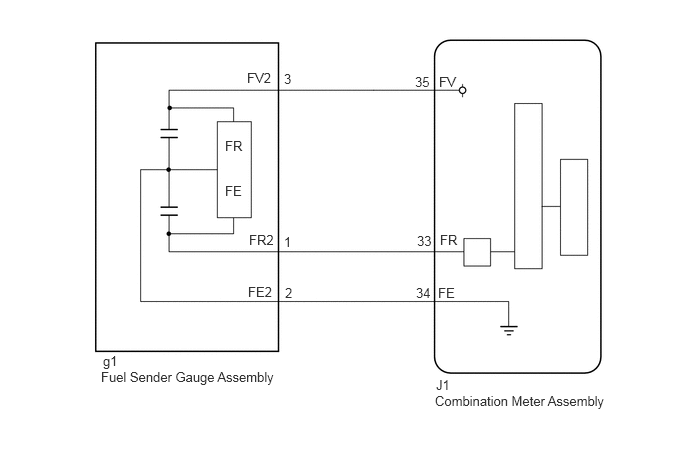
WIRING DIAGRAM
CAUTION / NOTICE / HINT
- NOTICE:
-
When replacing the combination meter assembly, always replace it with a new one. If a combination meter assembly which was installed to another vehicle is used, the information stored in it will not match the information from the vehicle and a DTC may be stored.
PROCEDURE
Using the GTS, read the Data List (Click hereVehicle Interior>METER / GAUGE / DISPLAY>METER / GAUGE SYSTEM>DATA LIST / ACTIVE TEST).
| Tester Display | Measurement Item / Range | Normal Condition | Diagnostic Note |
|---|---|---|---|
| Fuel Input | Fuel input / Min.: 0, Max.: 127.5 | Current fuel level displayed | Unit: Litter |
- OK:
Fuel level data displayed on the GTS is almost the same as the fuel receiver gauge assembly indication.
- Result:
Proceed to OK NG
OK
NG
Disconnect the J1 combination meter assembly connector.
Disconnect the g1 fuel sender gauge assembly connector.
Measure the resistance according to the value(s) in the table below.
- Standard Resistance:
Tester Connection Condition Specified Condition J1-35 (FV) - g1-3 (FV2) Always Below 1 Ω J1-34 (FE) - g1-2 (FE2) Always Below 1 Ω J1-33 (FR) - g1-1 (FR2) Always Below 1 Ω J1-35 (FV) - Body ground Always 10 kΩ or higher J1-34 (FE) - Body ground Always 10 kΩ or higher J1-33 (FR) - Body ground Always 10 kΩ or higher
- Result:
Proceed to OK NG
OK
NG
Remove the fuel sender gauge assembly.
for 2TR-FE:
Click hereEngine / Hybrid System>2TR-FE FUEL>FUEL SENDER GAUGE ASSEMBLY>REMOVAL
for N04C-UH:
Click hereEngine / Hybrid System>N04C-UH (FUEL)>FUEL SENDER GAUGE ASSEMBLY>REMOVAL
for N04C-VL:
Click hereEngine / Hybrid System>N04C-VL (FUEL)>FUEL SENDER GAUGE ASSEMBLY>REMOVAL
for N04C-VQ:
Click hereEngine / Hybrid System>N04C-VQ (FUEL)>FUEL SENDER GAUGE ASSEMBLY>REMOVAL
Inspect the fuel sender gauge assembly.
for 2TR-FE:
Click hereEngine / Hybrid System>2TR-FE FUEL>FUEL SENDER GAUGE ASSEMBLY>INSPECTION
for N04C-UH:
Click hereEngine / Hybrid System>N04C-UH (FUEL)>FUEL SENDER GAUGE ASSEMBLY>INSPECTION
for N04C-VL:
Click hereEngine / Hybrid System>N04C-VL (FUEL)>FUEL SENDER GAUGE ASSEMBLY>INSPECTION
for N04C-VQ:
Click hereEngine / Hybrid System>N04C-VQ (FUEL)>FUEL SENDER GAUGE ASSEMBLY>INSPECTION
- Result:
Proceed to OK NG
OK
NG
for 2TR-FE:
Click hereEngine / Hybrid System>2TR-FE FUEL>FUEL SENDER GAUGE ASSEMBLY>REMOVAL
for N04C-UH:
Click hereEngine / Hybrid System>N04C-UH (FUEL)>FUEL SENDER GAUGE ASSEMBLY>REMOVAL
for N04C-VL:
Click hereEngine / Hybrid System>N04C-VL (FUEL)>FUEL SENDER GAUGE ASSEMBLY>REMOVAL
for N04C-VQ:
Click hereEngine / Hybrid System>N04C-VQ (FUEL)>FUEL SENDER GAUGE ASSEMBLY>REMOVAL