A861E AUTOMATIC TRANSMISSION / TRANSAXLE VALVE BODY ASSEMBLY INSTALLATION
PROCEDURE

 1.INSTALL FRONT OIL PUMP ASSEMBLY
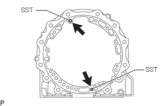
Install the SST to the automatic transmission assembly at 2 locations.
- SST
- 09390-36020

|
Install |
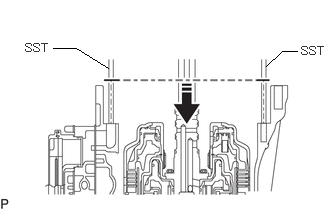
Install the new front oil pump cover gasket to the transmission case while passing the front oil pump cover gasket through the SST.
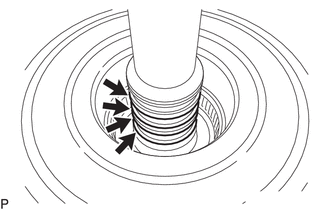
Install 4 new input shaft oil seal rings to the input shaft.
- NOTICE:
- ·
If the input shaft oil seal ring is assembled with a slightly reduced diameter before assembly, it will be difficult to pop out.
·After assembling the input shaft oil seal ring, check that the input shaft oil seal ring ends do not jump out for misaligning.
Apply MP grease to the 4 input shaft oil seal rings.
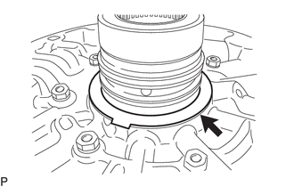
Install the clutch drum thrust washer to the front oil pump assembly.
- NOTICE:
- ·
Apply MP grease to the clutch drum thrust washer for preventing it dropped and broke.
·Pay attention to the tab direction because clutch drum thrust washer tab can only be in 1 place.
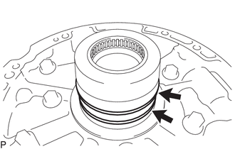
Apply MP grease to the 2 clutch drum oil seal rings.
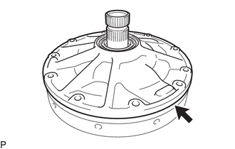
Apply MP grease to the O-ring.
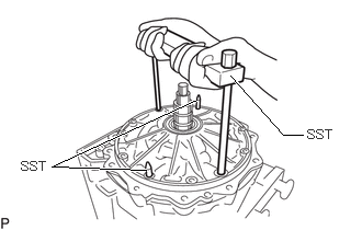
Using the SST, temporarily install the front oil pump assembly to the automatic transmission assembly while passing the SST through the screw hole of the front oil pump assembly.
- SST
- 09390-36010
- NOTICE:
- ·
Make sure that MP grease is applied to the O-ring on the outside edge of the front oil pump assembly.
·Using the SST, slowly lower the front oil pump assembly so that the O-ring, clutch drum oil seal ring and input shaft oil seal ring are not damaged.
·Align the bolt holes at an angle where the oil passage of the front oil pump assembly and the shape of the oil passage of the automatic transmission assembly align together, and lower the front oil pump assembly while passing through the SST.
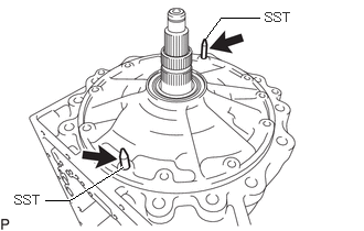
Remove the SST from the automatic transmission assembly at 2 locations.
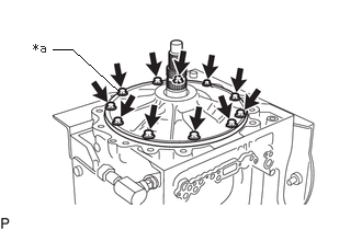
| *a | Standard Bolt |
Install the front oil pump assembly to the automatic transmission assembly with the 11 bolts.
- Torque:
- 21 N*m (214 kgf*cm, 15 ft.*lbf)
- NOTICE:
- ·
The first, temporarily tighten the standard bolt by hand to position the front oil pump assembly, and tighten the bolts alternately in a diagonal pattern to push into the front oil pump assembly gradually.
·Follow the "INPUT SHAFT END PLAY" procedure to apply the appropriate amount of adhesive 1324 to the bolt seats again and install the 11 bolts.
Rotate the SST to face the automatic transmission oil pan sub-assembly up.
2.INSPECT INPUT SHAFT END PLAY
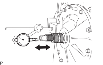
Using the dial gauge, apply the gauge to the tip of the input shaft.
Move the input shaft in the axial direction and measure the clearance.
- Standard End Play:
0.30 to 0.90 mm (0.0119 to 0.0354 in.)
- NOTICE:
- ·
The input shaft is slippery when it is moved. Make sure to thoroughly degrease it and wear gloves when performing work.
Do not use fabric gloves such as cotton work gloves.
·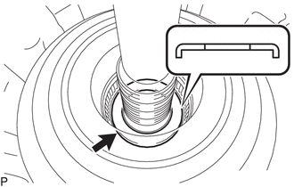
If the clearance is not specified, remove the front oil pump assembly, select and reinstall the thrust bearing race (input shaft front), and repeat steps 1 to 2.
Thrust Bearing Race (Input Shaft Front) Types Part No. Thickness 35789-37010 0.76 to 0.81 mm (0.0300 to 0.0318 in.) 35789-37020 1.07 to 1.13 mm (0.0422 to 0.0444 in.) 35789-37030 1.56 to 1.64 mm (0.0615 to 0.0645 in.)
·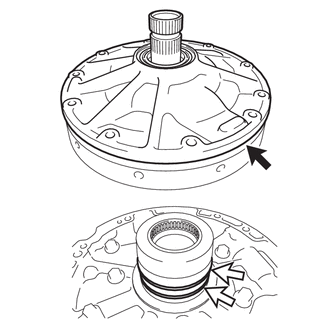 0,0 0,0 false

O-Ring 
Clutch Drum Oil Seal Ring
If the front oil pump assembly was removed according to the inspection results, replace the 2 clutch drum oil seal rings and O-ring with a new part and apply MP grease.
-If the clutch drum oil seal ring is assembled with a slightly reduced diameter before assembly, it will be difficult to pop out.
-After assembling the clutch drum oil seal ring, check that the clutch drum oil seal ring ends do not jump out for misaligning.
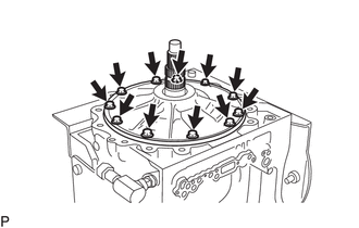
Remove the 11 bolts, apply the appropriate amount of adhesive 1324 to the bolt seats, and install the 11 bolts again.
- Torque:
- 21 N*m (214 kgf*cm, 15 ft.*lbf)
3.INSTALL AUTOMATIC TRANSMISSION HOUSING
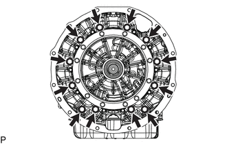
Install the automatic transmission housing to the automatic transmission assembly with the 12 bolts.
- Torque:
- 64 N*m (653 kgf*cm, 47 ft.*lbf)
35712A
4.INSTALL INPUT SHAFT OIL SEAL RING
5.INSTALL ACCUMULATOR PISTON AND ACCUMULATOR SPRING SUB-ASSEMBLY
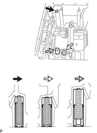
|
|
No. 1 Accumulator Piston and Accumulator Spring Sub-assembly |
|
|
No. 2 Accumulator Piston and Accumulator Spring Sub-assembly |

|
No. 3 Accumulator Piston and Accumulator Spring Sub-assembly |
Install the No. 1 accumulator piston and No. 2 accumulator piston, No. 3 accumulator piston, 3 accumulator spring sub-assemblies.
- NOTICE:
- ·
The accumulator piston and accumulator spring sub-assembly may fall if the transmission assembly is tilted down.
·There are different types of accumulator pistons and accumulator spring sub-assemblies. Be careful not to mistake the type.
Accumulator Types Spring Color Spring Free Length Accumulator Piston Diameter Accumulator Piston Length No. 1 accumulator piston and accumulator spring sub-assembly Purple 43.27 mm (1.70 in.) 16 mm (0.630 in.) 40.18 mm (1.58 in.) No. 2 accumulator piston and accumulator spring sub-assembly Yellow 50.12 mm (1.97 in.) 20 mm (0.787 in.) 39.18 mm (1.54 in.) No. 3 accumulator piston and accumulator spring sub-assembly Green 68.18 mm (2.68 in.) 20 mm (0.787 in.) 38.18 mm (1.50 in.)
6.INSTALL TRANSMISSION VALVE BODY ASSEMBLY
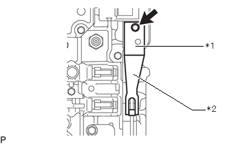
| *1 | Manual Detent Spring Cover |
| *2 | Manual Detent Spring Sub-assembly |
Temporarily install the manual detent spring cover and manual detent spring sub-assembly to the transmission valve body assembly with the bolt and washer.
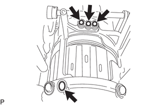
Install 4 new valve body gaskets to the automatic transmission assembly.
After inserting the tip of the manual valve into the groove of the manual valve lever, place the transmission valve body assembly on the automatic transmission assembly.
- CAUTION:
-
Perform working with holding the side surfaces with a finger not to trap the finger by the automatic transmission assembly and the transmission valve body assembly.
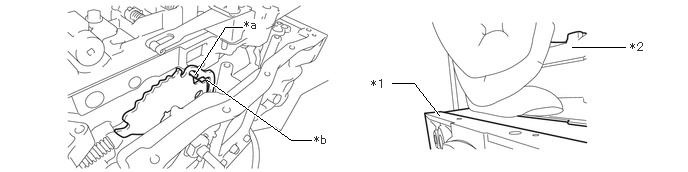
| *1 | Automatic Transmission Assembly | *2 | Transmission Valve Body Assembly |
| *a | Tip of the Manual Valve | *b | Groove of the Manual Valve Lever |
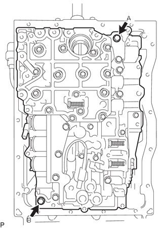
Slowly move the transmission valve body assembly to align it with the bolt holes and temporarily install with the 2 bolts in the positions shown in the illustration.
- HINT:
Bolt Type Bolt Shape Under Head Length A Flange Bolt 58 mm (2.28 in.) B Flange Bolt 31.2 mm (1.23 in.)
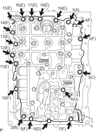
| *1 | Valve Body Wire Harness Clamp |
Install transmission valve body assembly and valve body wire harness clamp to the automatic transmission assembly with the 19 bolts.
- Torque:
- 10 N*m (102 kgf*cm, 7 ft.*lbf)
- HINT:
-
Tighten the bolts in the order shown in the illustration.
Tightening Order Bolt Type Bolt Shape Under Head Length 1 A Flange Bolt 58 mm (2.28 in.) 2 B Flange Bolt 31.2 mm (1.23 in.) 3 C Flange Bolt 43 mm (1.69 in.) 8 D Bolt with Washer 42.5 mm (1.67 in.) 11, 12, 13, 14, 15, 16, 17, 18, 19 E Bolt with Washer 57.2 mm (2.25 in.) 4, 5, 7, 9, 10 F Bolt with Washer 32.2 mm (1.27 in.) 6 G Bolt with Washer 51 mm (2.01 in.)
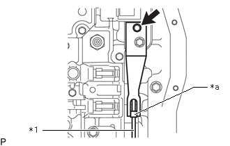
| *1 | Manual Lever |
| *a | Manual Detent Spring Sub-assembly Roller |
Tighten the bolt.
- Torque:
- 5.5 N*m (56 kgf*cm, 49 in.*lbf)
- NOTICE:
-
Check that the manual detent spring sub-assembly roller and manual lever are not misaligned. If they are, loosen the 2 bolts securing the manual detent spring sub-assembly and adjust the position.
83380A
7.INSTALL NO. 8 OIL PRESSURE SWITCH
83380A
8.INSTALL NO. 7 OIL PRESSURE SWITCH
83380A
9.INSTALL NO. 6 OIL PRESSURE SWITCH
83380A
10.INSTALL NO. 3 OIL PRESSURE SWITCH
83380A
11.INSTALL NO. 2 OIL PRESSURE SWITCH
83380A
12.INSTALL NO. 1 OIL PRESSURE SWITCH
13.INSTALL SHIFT SOLENOID VALVE S4
14.INSTALL SHIFT SOLENOID VALVE S3
35240F
15.INSTALL SHIFT SOLENOID VALVE S2
35240E
16.INSTALL SHIFT SOLENOID VALVE S1
17.INSTALL TRANSMISSION WIRE
35330
18.INSTALL VALVE BODY OIL STRAINER ASSEMBLY
35168
19.INSTALL AUTOMATIC TRANSMISSION OIL PAN GASKET
35106
20.INSTALL AUTOMATIC TRANSMISSION OIL PAN SUB-ASSEMBLY
Install the automatic transmission oil pan sub-assembly.
Click hereDrivetrain>A861E (AUTOMATIC TRANSMISSION / TRANSAXLE)>OIL PAN GASKET>REPLACEMENT
Rotate the SST to face the automatic transmission oil pan sub-assembly down.
Remove SST from engine stand.
Remove the 4 bolts and automatic transmission assembly from SST.
33161B
21.INSTALL TRANSMISSION POWER TAKE-OFF COVER
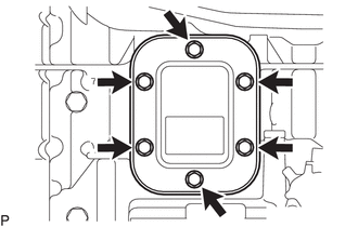
Clean the sealant from the installation bolt of the transmission power take-off cover and let it dry.
Clean the bolts and bolt holes.
Install the transmission power take-off cover to the automatic transmission assembly with a new gasket and the 6 bolts.
- Torque:
- 15 N*m (153 kgf*cm, 11 ft.*lbf)
32000
22.INSTALL TORQUE CONVERTER ASSEMBLY
35000
23.INSTALL AUTOMATIC TRANSMISSION ASSEMBLY
24. TEST DRIVE
If a DTC is generated after performing a test drive or shift shock becomes worse, replace the automatic transmission assembly.
25. RESET MEMORY
- NOTICE:
-
If automatic transmission parts have been replaced, refer to the Parts Replacement Compensation Table to determine if any additional operations are necessary.
-
Click hereDrivetrain>A861E (AUTOMATIC TRANSMISSION / TRANSAXLE)>AUTOMATIC TRANSMISSION SYSTEM>INITIALIZATION