A861E AUTOMATIC TRANSMISSION / TRANSAXLE AUTOMATIC TRANSMISSION ASSEMBLY INSTALLATION
PROCEDURE

 35301A
1.INSTALL FRONT OIL PUMP OIL SEAL
Coat the lip of a new front oil pump oil seal with MP grease.
- NOTICE:
-
Do not allow foreign matter to attach to the lip of the front oil pump oil seal.
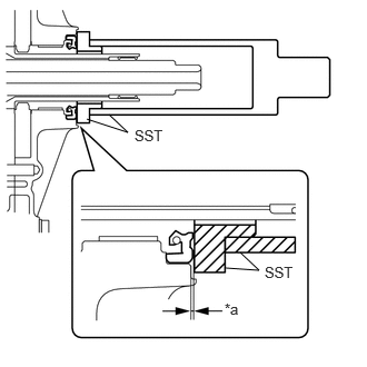
| *a | 0 to 0.1 mm (0 to 0.00393 in.) |
Using SST, install a new front oil pump oil seal to the front oil pump assembly.
- SST
- 09950-70010 (09951-07150)
09649-17010
- Standard Depth:
0 to 0.1 mm (0 to 0.00393 in.)
- NOTICE:
- ·
Keep the lip free from foreign matter.
·Do not allow oil to adhere to the outside of the front oil pump oil seal.
·Do not tap in the front oil pump oil seal at an angle.
·Wipe off any MP grease adhering to the front oil pump assembly.
35712A
2.INSTALL INPUT SHAFT OIL SEAL RING
Coat a new input shaft oil seal ring with MP grease.
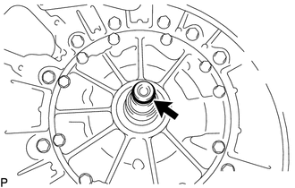
Install the input shaft oil seal ring to the input shaft sub-assembly.
32000
3.INSTALL TORQUE CONVERTER ASSEMBLY
Attach the splines of the input shaft with the turbine runner splines.
Rotate the torque converter assembly approximately 180° and engage the splines of the stator shaft with the stator assembly.
- HINT:
-
If it is difficult to engage the splines of the stator shaft with the stator assembly, reverse the torque converter assembly approximately 10 mm, rotate the torque converter assembly again.
Rotate the torque converter assembly and engage the key of the stator shaft and key of the torque converter assembly with the torque converter assembly.
- NOTICE:
-
Do not push the torque converter assembly excessively when rotating it.
Clean the drive plate and torque converter assembly setting bolt holes.
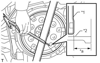
| *1 | Drive Plate |
| *2 | Flywheel Housing |
| *a | Dimension (A) |
Using a vernier caliper and straightedge, measure the dimension (A) between the automatic transmission assembly and the end surface of the drive plate [*1].
- NOTICE:
-
Make sure to deduct the thickness of the straightedge.
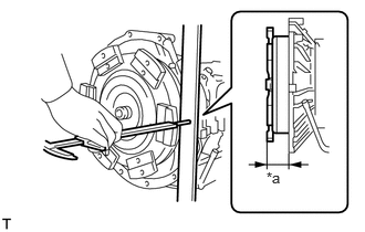
| *a | Dimension (B) |
Using a vernier caliper and a straightedge, measure dimension (B) shown in the illustration and check that (B) is smaller than (A) measured in step [*1].
- Standard:
(B) = (A) - 1 mm (0.0394 in.) or more
- NOTICE:
- ·
If the automatic transmission assembly is installed to the flywheel housing with the torque converter assembly not sufficiently inserted, the torque converter assembly may be damaged.
·Make sure to deduct the thickness of the straightedge.
12371A
4.INSTALL REAR ENGINE MOUNTING INSULATOR
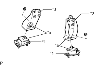
| *1 | Rear Engine Mounting Insulator |
| *2 | Rear Engine Mounting Bracket LH |
| *3 | Rear Engine Mounting Bracket RH |
| *a | Align the rear engine mounting bracket LH hole and rear engine mounting bracket RH hole with the protrusion of the rear engine mounting insulator. |
Install the 2 rear engine mounting insulators to the rear engine mounting bracket LH and rear engine mounting bracket RH with the 2 nuts.
- Torque:
- 74 N*m (755 kgf*cm, 55 ft.*lbf)
12321F
5.INSTALL REAR ENGINE MOUNTING BRACKET RH
Install the rear engine mounting bracket RH to the automatic transmission assembly with the 4 bolts.
- Torque:
- 44 N*m (449 kgf*cm, 32 ft.*lbf)
12325C
6.INSTALL REAR ENGINE MOUNTING BRACKET LH
Install the rear engine mounting bracket LH to the automatic transmission assembly with the 4 bolts.
- Torque:
- 44 N*m (449 kgf*cm, 32 ft.*lbf)
35000
7.INSTALL AUTOMATIC TRANSMISSION ASSEMBLY
Make sure that the 2 knock pins are on engine side.
Hold the engine and automatic transmission assembly horizontally and then engage the knock pins.
Install the automatic transmission assembly to the engine assembly with the 12 bolts.
- Torque:
- 43.1 N*m (439 kgf*cm, 32 ft.*lbf)
- NOTICE:
- ·
Check whether the torque converter assembly turns by hand.
·Do not use excess force when installing the automatic transmission assembly.
51204
8.INSTALL NO. 3 FRAME CROSSMEMBER SUB-ASSEMBLY
Install the No. 3 frame crossmember sub-assembly to the 2 rear engine mounting insulators with the 4 nuts and 4 washers.
- Torque:
- 56 N*m (571 kgf*cm, 41 ft.*lbf)
Connect the No. 3 frame crossmember sub-assembly to the frame with the 12 bolts.
- Torque:
- 50 N*m (510 kgf*cm, 37 ft.*lbf)
32101A
9.INSTALL DRIVE PLATE AND TORQUE CONVERTER SETTING BOLT
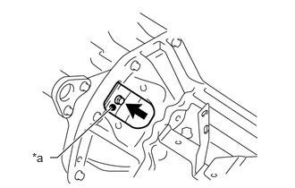
| *a | Identification Paint |
Insert a screwdriver into the ring gear of the flywheel sub-assembly from the flywheel housing check hole and hold the crankshaft.
Install the torque converter assembly to the drive plate with the 6 drive plate and torque converter setting bolts.
- Torque:
- 54 N*m (551 kgf*cm, 40 ft.*lbf)
- HINT:
- ·
Install the drive plate and torque converter setting bolts through the hole in the transmission case dust cover sub-assembly.
·Install the torque converter assembly starting with the areas marked by paint marks.
·Tighten the 6 drive plate and torque converter setting bolts equally.
·Use the inspection hole in the flywheel housing to rotate the drive plate.
35019
10.INSTALL TRANSMISSION CASE DUST COVER SUB-ASSEMBLY
Install the transmission case dust cover sub-assembly to the automatic transmission assembly with the 2 bolts.
- Torque:
- 17.5 N*m (178 kgf*cm, 13 ft.*lbf)
11.INSTALL WIRE HARNESS CLAMP BRACKET
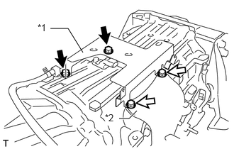
| *1 | Wire Harness Clamp Bracket |
| *2 | No. 1 Transmission Control Cable Bracket |

|
Bolt A |

|
Bolt B |
Install the wire harness clamp bracket and No. 1 transmission control cable bracket to the automatic transmission assembly with the 4 bolts.
- Torque:
- for bolt A : 12 N*m (122 kgf*cm, 9 ft.*lbf)
- for bolt B : 14 N*m (143 kgf*cm, 10 ft.*lbf)
12.CONNECT CONNECTORS
Connect the park/neutral position switch assembly connector and 2 transmission wire connectors to the automatic transmission assembly.
Connect the transmission revolution sensor connector to the automatic transmission assembly.
Connect the temperature sensor connector to the automatic transmission assembly.
35013
13.INSTALL TRANSMISSION OIL FILLER TUBE SUB-ASSEMBLY
Coat a new O-ring with Toyota Genuine ATF type T-IV, and install it to the transmission oil filler tube sub-assembly.
Install the transmission oil filler tube sub-assembly to the automatic transmission assembly with the 2 bolts.
- Torque:
- 12 N*m (122 kgf*cm, 9 ft.*lbf)
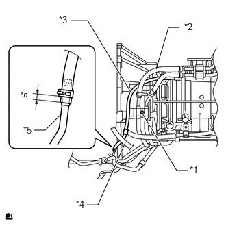
| *1 | Oil Cooler Hose Bracket |
| *2 | Oil Cooler Hose |
| *3 | Breather Hose |
| *4 | Transmission Control Cable Assembly |
| *5 | Transmission Oil Filler Tube Sub-assembly |
| *a | 6 mm (0.236 in.) |
Connect the breather hose to the transmission oil filler tube sub-assembly shown in the illustration.
- NOTICE:
- ·
Pass the breather hose under the oil cooler hose so that the hoses do not contact each other.
·Pass the breather hose under the transmission control cable assembly.
·Pass the breather hose under the engine wire.
·Make sure that the breather hose is closer to the front of the vehicle than the oil cooler hose bracket.
·Be careful not to twist the breather hose.
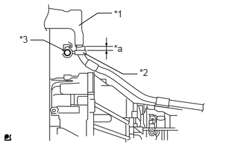
| *1 | Wire Harness Protector |
| *2 | Hose Clamp |
| *3 | Breather Hose |
| *a | 5 to 10 mm (0.197 to 0.393 in.) |
Position the hose clamp that is installed to the engine wire as shown in the illustration and install the marked part of the breather hose with the clamp.
- HINT:
-
The marking is white.
Install the transmission oil level dipstick sub-assembly to the transmission oil filler tube sub-assembly.
33820B
14.CONNECT TRANSMISSION CONTROL CABLE ASSEMBLY
Connect the transmission control cable assembly with the bolt.
- Torque:
- 14 N*m (143 kgf*cm, 10 ft.*lbf)
Press the transmission control shaft lever LH toward the rear of the vehicle until it stops, and then move it back 2 steps (N position).
Connect the transmission control cable assembly to the transmission control shaft lever LH and transmission control cable bracket with the nut, washer and a new clip.
- Torque:
- 14 N*m (143 kgf*cm, 10 ft.*lbf)
- NOTICE:
- ·
Move the shift lever to N, and lightly put it on the P position side.
·While holding the shift lever in that position, pull the transmission control cable assembly toward the rear of the vehicle and secure the transmission control cable assembly and transmission control shaft lever LH.
15.INSTALL OIL COOLER HOSE
Install the oil cooler hoses and slide the 8 clips to secure the hose as shown in the illustration.
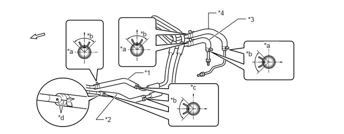
| *1 | No. 1 Oil Cooler Inlet Hose | *2 | No. 1 Oil Cooler Outlet Hose |
| *3 | No. 2 Oil Cooler Inlet Hose | *4 | No. 2 Oil Cooler Outlet Hose |
| *a | Front of the Vehicle | *b | 90° |
| *c | Upper Side of Vehicle | *d | Paint Mark |
|
|
Front of the Vehicle | - | - |
- NOTICE:
-
Make sure to align the paint mark of the No. 1 oil cooler outlet hose with the paint mark of the No. 1 oil cooler outlet tube when installing the No. 1 oil cooler outlet hose.
32921
16.CONNECT NO. 1 OIL COOLER INLET TUBE
Install the oil cooler tube clamp to the automatic transmission assembly with the bolt.
- Torque:
- 12 N*m (122 kgf*cm, 9 ft.*lbf)
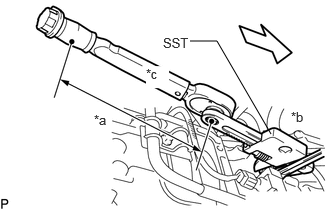
| *a | Torque Wrench Fulcrum Length |
| *b | Hold |
| *c | Turn |
|
|
Front of the Vehicle |
Hold the oil cooler tube union with a wrench and using SST, connect the No. 1 oil cooler inlet tube to the automatic transmission assembly.
- SST
- 09922-10010
- Torque:
- Specified tightening torque : 69 N*m (704 kgf*cm, 51 ft.*lbf)
- HINT:
- ·
Do not using direction SST.
·Install the part so that SST and the torque wrench are in a straight line.
·Calculate the torque wrench reading when changing the fulcrum length of the torque wrench.
·When using a SST (fulcrum length of 136 mm (5.3543 in.)) + torque wrench (fulcrum length of 255 mm (10.0394 in.)): 45 N*m (459 kgf*cm, 33 ft.*lbf)
32922
17.CONNECT NO. 1 OIL COOLER OUTLET TUBE
Install the oil cooler tube clamp to the automatic transmission assembly with the bolt.
- Torque:
- 24 N*m (245 kgf*cm, 18 ft.*lbf)
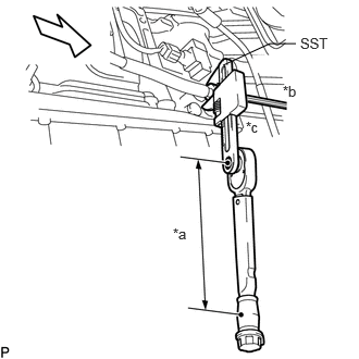
| *a | Torque Wrench Fulcrum Length |
| *b | Hold |
| *c | Turn |
|
|
Front of the Vehicle |
Hold the oil cooler tube union with a wrench and using SST, connect the No. 1 oil cooler outlet tube to the automatic transmission assembly.
- SST
- 09922-10010
- Torque:
- Specified tightening torque : 69 N*m (704 kgf*cm, 51 ft.*lbf)
- HINT:
- ·
Do not using direction SST.
·Install the part so that SST and the torque wrench are in a straight line.
·Calculate the torque wrench reading when changing the fulcrum length of the torque wrench.
·When using a SST (fulcrum length of 136 mm (5.3543 in.)) + torque wrench (fulcrum length of 255 mm (10.0394 in.)): 45 N*m (459 kgf*cm, 33 ft.*lbf)
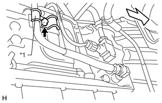
| *1 | No. 2 Oil Cooler Tube Clamp |
|
|
Front of the Vehicle |
Install the No. 2 oil cooler tube clamp to the automatic transmission assembly with the bolt.
- Torque:
- 12 N*m (122 kgf*cm, 9 ft.*lbf)
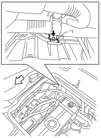
| *1 | No. 2 Oil Cooler Tube Clamp |
|
|
Front of the Vehicle |
Install the No. 2 oil cooler tube clamp to the automatic transmission assembly with the bolt.
- Torque:
- 12 N*m (122 kgf*cm, 9 ft.*lbf)
Install the 2 oil cooler tube clamps and No. 3 oil cooler tube clamp to the automatic transmission assembly with the 3 bolts.
- Torque:
- 12 N*m (122 kgf*cm, 9 ft.*lbf)
46503C
18.CONNECT PARKING BRAKE PLATE SUB-ASSEMBLY
Clean the bolt and bolt hole, degrease the application surface with a non-residue solvent, and then dry with compressed air.
Apply adhesive 1344 at 2 or 3 threads from the end of the parking brake assembly installation bolt.
Connect the parking brake assembly to the extension housing with the 4 bolts.
- Torque:
- 95 N*m (969 kgf*cm, 70 ft.*lbf)
Tighten the adjusting nut to the parking brake cable.
- Torque:
- 5.4 N*m (55 kgf*cm, 48 in.*lbf)
46241
19.INSTALL PARKING BRAKE LEVER BOOT
46243
20.INSTALL PARKING BRAKE LEVER COVER
46501
21.INSTALL PARKING BRAKE DRUM SUB-ASSEMBLY
22.ADJUST BRAKE SHOE CLEARANCE
23.INSPECT PARKING BRAKE LEVER
24.ADJUST PARKING BRAKE LEVER
25.INSTALL FRONT EXHAUST PIPE ASSEMBLY
37140
26.INSTALL PROPELLER SHAFT ASSEMBLY
27.CONNECT CABLE TO NEGATIVE BATTERY TERMINAL
28.ADD AUTOMATIC TRANSMISSION FLUID
29.INSPECT AUTOMATIC TRANSMISSION FLUID LEAK
30.INSPECT AUTOMATIC TRANSMISSION FLUID LEVEL
58734B
31.INSTALL REAR ENGINE SERVICE COVER WEATHERSTRIP
58410
32.INSTALL ENGINE SERVICE HOLE COVER
58420
33.INSTALL NO. 2 ENGINE SERVICE HOLE COVER ASSEMBLY
58521D
34.INSTALL ENGINE SERVICE HOLE COVER MAT
51441D
35.INSTALL NO. 1 ENGINE UNDER COVER
36.INSPECT FOR EXHAUST GAS LEAK
37. RESET MEMORY
- NOTICE:
-
If automatic transmission parts have been replaced, refer to the Parts Replacement Compensation Table to determine if any additional operations are necessary.
-
Click hereDrivetrain>A861E (AUTOMATIC TRANSMISSION / TRANSAXLE)>AUTOMATIC TRANSMISSION SYSTEM>INITIALIZATION