AIR CONDITIONING AIR CONDITIONING PANEL REMOVAL
CAUTION / NOTICE / HINT
- HINT:
- ·
Use the same procedure for LHD and RHD vehicles.
·The procedure listed below is for RHD vehicles.
PROCEDURE

 55410C
1.REMOVE INSTRUMENT CLUSTER FINISH PANEL ASSEMBLY
58841A
2.REMOVE SHIFTING HOLE COVER (for Automatic Transmission)
for A444E:
Click hereDrivetrain>A444E (AUTOMATIC TRANSMISSION / TRANSAXLE)>FLOOR SHIFT ASSEMBLY>REMOVAL
for A861E:
Click hereDrivetrain>A861E (AUTOMATIC TRANSMISSION / TRANSAXLE)>FLOOR SHIFT ASSEMBLY>REMOVAL
33504F
3.REMOVE SHIFT LEVER KNOB SUB-ASSEMBLY (for Manual Transmission)
58534A
4.REMOVE TRANSMISSION COVER MAT (for Manual Transmission)
58286
5.REMOVE NO. 1 SHIFT AND SELECT LEVER BOOT (for Manual Transmission)
58123A
6.REMOVE SHIFT AND SELECT LEVER SUPPORT (for Manual Transmission)
55433B
7.REMOVE LOWER NO. 2 INSTRUMENT PANEL FINISH PANEL
86250
8.REMOVE AMPLIFIER MICROPHONE ASSEMBLY (w/ Microphone)
55412D
9.REMOVE CENTER INSTRUMENT CLUSTER FINISH PANEL
55470
10.REMOVE INSTRUMENT CLUSTER FINISH PANEL GARNISH ASSEMBLY
55601C
11.REMOVE INSTRUMENT PANEL UNDER TRAY SUB-ASSEMBLY
85330
12.REMOVE WINDSHIELD WASHER JAR ASSEMBLY
55900
13.REMOVE AIR CONDITIONING CONTROL ASSEMBLY
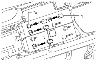
Set the defroster damper control lever in "DEF mode".
Set the air inlet damper control lever in "RECIRC mode".
Set the air mix damper control lever in "COOL mode".
Set the water valve control lever in "COOL mode".
| *a | Defroster Damper Control Lever |
| *b | Air Inlet Damper Control Lever |
| *c | Air Mix Damper Control Lever |
| *d | Water Valve Control Lever |
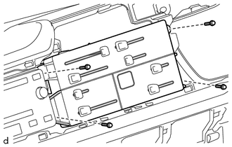
Remove the 4 bolts.
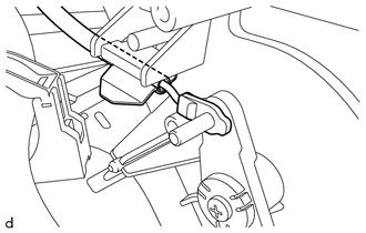
Disconnect the air inlet damper control cable sub-assembly:
Disconnect the air inlet damper control cable sub-assembly on the heater assembly side.
- NOTICE:
-
Attach a piece of string to the end of the disconnected air inlet damper control cable sub-assembly to use as a guide when installing.
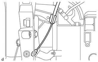
Disconnect the defroster damper control cable sub-assembly:
Disconnect the defroster damper control cable sub-assembly on the heater assembly side.
- NOTICE:
-
Attach a piece of string to the end of the disconnected defroster damper control cable sub-assembly to use as a guide when installing.
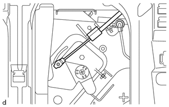
Disconnect the air mix damper control cable sub-assembly:
Disconnect the air mix damper control cable sub-assembly on the heater assembly side.
- NOTICE:
-
Attach a piece of string to the end of the disconnected air mix damper control cable sub-assembly to use as a guide when installing.
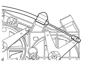
Disconnect the air inlet damper control cable sub-assembly:
Disconnect the air inlet damper control cable sub-assembly on the air conditioner control assembly side.
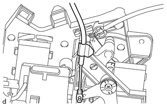
Disconnect the water valve control cable sub-assembly:
Disconnect the water valve control cable sub-assembly on the air conditioner control assembly side.
Disconnect the connectors and remove the air conditioner control assembly.