INTERIOR PANEL INSTRUMENT PANEL SAFETY PAD REMOVAL
CAUTION / NOTICE / HINT
- HINT:
- ·
Use the same procedure for RHD and LHD vehicles.
·The procedure listed below is for RHD vehicles.
PROCEDURE

 1. TABLE OF BOLT,SCREW,NUT AND CLIP
- HINT:
-
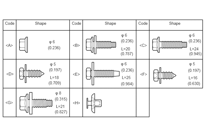
All bolts, nuts, and screws and clips relevant to installing and removing the instrument panel are shown along with their alphabet code in the table below.
 0.177,0.729 0.615,0.927 0.438,0.198 10 false Code 1.219,0.729 1.656,0.927 0.438,0.198 10 false Shape 2.5,0.729 2.938,0.927 0.438,0.198 10 false Code 4.813,0.729 5.25,0.927 0.438,0.198 10 false Code 3.646,0.729 4.083,0.927 0.438,0.198 10 false Shape 5.885,0.729 6.323,0.927 0.438,0.198 10 false Shape 0.198,1.5 0.635,1.698 0.438,0.198 10 false <A> 1.708,1.375 2.146,1.573 0.438,0.198 10 false φ 6 1.667,1.583 2.104,1.781 0.438,0.198 10 false (0.236) 4.219,1.146 4.656,1.344 0.438,0.198 10 false φ 6 6.573,1.146 7.01,1.344 0.438,0.198 10 false φ 6 4.208,2.146 4.646,2.344 0.438,0.198 10 false φ 6 4.208,1.344 4.646,1.542 0.438,0.198 10 false (0.236) 6.563,1.344 7,1.542 0.438,0.198 10 false (0.236) 4.219,2.365 4.656,2.563 0.438,0.198 10 false (0.236) 0.219,2.5 0.656,2.698 0.438,0.198 10 false <D> 0.188,3.5 0.625,3.698 0.438,0.198 10 false <G> 2.531,1.5 2.969,1.698 0.438,0.198 10 false <B> 4.854,1.5 5.292,1.698 0.438,0.198 10 false <C> 2.531,2.51 2.969,2.708 0.438,0.198 10 false <E> 4.875,2.51 5.313,2.708 0.438,0.198 10 false <F> 2.531,3.51 2.969,3.708 0.438,0.198 10 false <H> 1.74,2.156 2.177,2.354 0.438,0.198 10 false φ 5 6.583,2.146 7.021,2.344 0.438,0.198 10 false φ 5 1.927,3.167 2.365,3.365 0.438,0.198 10 false φ 8 1.708,2.354 2.26,2.604 0.552,0.25 10 false (0.197) 6.542,2.375 7.094,2.625 0.552,0.25 10 false (0.197) 1.74,2.625 2.177,2.823 0.438,0.198 10 false L=18 1.688,2.813 2.188,3.01 0.5,0.198 10 false (0.709) 4.24,2.625 4.677,2.823 0.438,0.198 10 false L=25 4.219,1.625 4.656,1.823 0.438,0.198 10 false L=20 6.604,1.625 7.042,1.823 0.438,0.198 10 false L=24 6.563,2.635 7,2.833 0.438,0.198 10 false L=16 1.948,3.635 2.385,3.833 0.438,0.198 10 false L=21 1.906,3.375 2.344,3.573 0.438,0.198 10 false (0.315) 1.906,3.823 2.344,4.021 0.438,0.198 10 false (0.827) 4.198,1.792 4.635,1.99 0.438,0.198 10 false (0.787) 4.208,2.844 4.646,3.042 0.438,0.198 10 false (0.984) 6.531,2.833 7.083,3.083 0.552,0.25 10 false (0.630) 6.583,1.792 7.135,2.042 0.552,0.25 10 false (0.945)
2. PRECAUTION
- NOTICE:
-
After turning the ignition switch off, waiting time may be required before disconnecting the cable from the battery terminal. Therefore, make sure to read the disconnecting the cable from the battery terminal notice before proceeding with work.
-
Click hereGeneral>INTRODUCTION>REPAIR INSTRUCTION>PRECAUTION
3.DISCONNECT CABLE FROM NEGATIVE BATTERY TERMINAL
- CAUTION:
-
Wait at least 90 seconds after disconnecting the cable from the negative (-) battery terminal to disable the the SRS system.
- NOTICE:
-
When disconnecting the cable, some systems need to be initialized after the cable is reconnected.
-
Click hereGeneral>INTRODUCTION>REPAIR INSTRUCTION>INITIALIZATION
74617V
4.REMOVE ASSIST GRIP PLUG
74603
5.REMOVE FRONT ASSIST GRIP SUB-ASSEMBLY
62311C
6.DISCONNECT FRONT DOOR OPENING TRIM WEATHERSTRIP RH
- HINT:
-
Disconnect the front door opening trim weatherstrip RH so that front pillar garnish RH can be removed.
62211
7.REMOVE FRONT PILLAR GARNISH RH
62212
8.REMOVE FRONT PILLAR GARNISH LH
- HINT:
-
Use the same procedure described for the RH side.
33504F
9.REMOVE SHIFT LEVER KNOB SUB-ASSEMBLY (for Manual Transmission)
Remove the shift lever knob sub-assembly.
58534A
10.REMOVE TRANSMISSION COVER MAT (for Manual Transmission)
Remove the transmission cover mat from the shift and select lever support.
33555D
11.REMOVE SHIFT LEVER BOOT (for Manual Transmission)
58848A
12.REMOVE SHIFT LEVER HOLE COVER (for Manual Transmission)
58841A
13.REMOVE SHIFTING HOLE COVER (for Automatic Transmission)
55433B
14.REMOVE LOWER NO. 2 INSTRUMENT PANEL FINISH PANEL
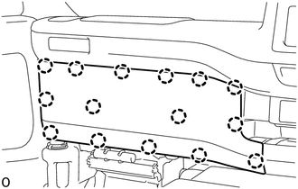
Detach the 15 claws and remove the lower No. 2 instrument panel finish panel.
86250
15.REMOVE AMPLIFIER MICROPHONE ASSEMBLY (w/ Microphone)
55412D
16.REMOVE CENTER INSTRUMENT CLUSTER FINISH PANEL
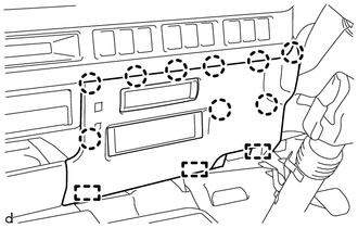
Detach the 9 claws and 3 guides and remove the center instrument cluster finish panel.
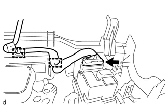
w/ Outer Mirror Control Switch:
Detach the 2 clamps and disconnect the connector.
86290A
17.REMOVE MICROPHONE AMPLIFIER ASSEMBLY (w/ Microphone)
55521C
18.REMOVE STEREO OPENING COVER (w/o Microphone)
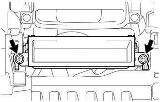
Remove the 2 screws and stereo opening cover.
55845B
19.REMOVE REAR NO. 3 HEATER TO REGISTER DUCT (w/ Heater)
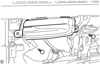
Remove the 2 clips and rear No. 3 heater to register duct.
55480D
20.REMOVE LOWER INSTRUMENT PANEL FINISH PANEL ASSEMBLY
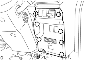
Remove the bolt <B>.
Detach the 7 claws and remove the lower instrument panel finish panel assembly.
Disconnect each connector.
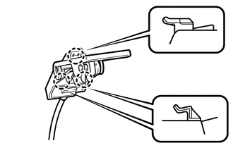
for LHD, w/ Fuel Lid Opener:
Detach the 3 claws and disconnect the fuel lid lock control cable assembly.
55470
21.REMOVE INSTRUMENT CLUSTER FINISH PANEL GARNISH ASSEMBLY
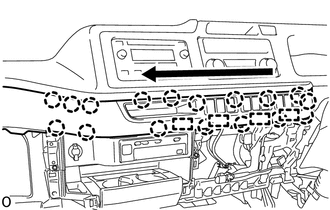
Detach the 17 claws and 4 guides as indicated by the arrow in the order shown in the illustration.
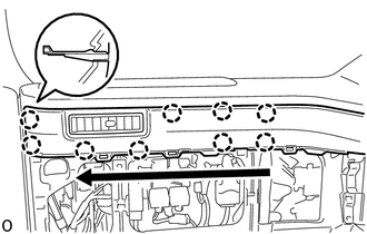
Detach the 9 claws as indicated by the arrow in the order shown in the illustration and remove the instrument cluster finish panel garnish assembly.
Disconnect each connector.
55601C
22.REMOVE INSTRUMENT PANEL UNDER TRAY SUB-ASSEMBLY
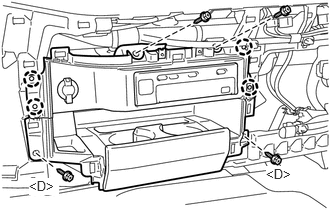
w/ Tachograph:
Remove the 2 screws <D> and 2 screws.
Detach the 4 claws and remove the instrument panel under tray sub-assembly.
Disconnect the connector.
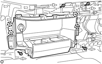
w/o Tachograph:
Remove the 4 screws <D>.
Detach the 4 claws and remove the instrument panel under tray sub-assembly.
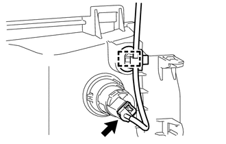
Detach the clamp and disconnect the connector.
83210
23.REMOVE TACHOGRAPH ASSEMBLY (w/ Tachograph)
55458B
24.REMOVE LOWER INSTRUMENT COVER
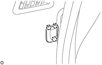
Detach the 3 claws and remove the lower instrument cover.
55961A
25.REMOVE SIDE DEFROSTER NOZZLE RH (w/ Heater)
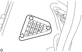
Detach the 3 claws and remove the side defroster nozzle RH.
55959A
26.REMOVE NO. 1 DEFROSTER NOZZLE OPENING COVER (w/o Heater)
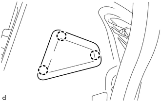
Detach the 3 claws and remove the No. 1 defroster nozzle opening cover.
55432C
27.REMOVE RESERVOIR TANK DOOR
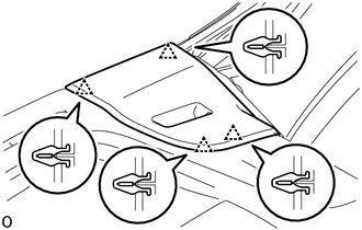
Detach the 4 clips and remove the reservoir tank door.
55410C
28.REMOVE INSTRUMENT CLUSTER FINISH PANEL ASSEMBLY
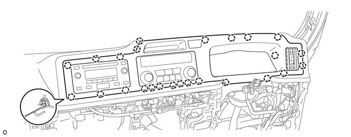
Detach the 25 claws and remove the instrument cluster finish panel assembly.
Disconnect the connector.
83100
29.REMOVE COMBINATION METER ASSEMBLY
86120
30.REMOVE RADIO RECEIVER ASSEMBLY (w/ Audio)
55522B
31.REMOVE RADIO TUNER OPENING COVER (w/o Audio)
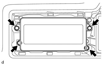
Remove the 4 bolts and radio tuner opening cover.
55900
32.REMOVE AIR CONDITIONING CONTROL ASSEMBLY (w/ Air Control Panel)
55523
33.REMOVE HEATER CONTROL OPENING COVER (w/o Air Control Panel)
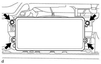
Remove the 4 bolts <C> and heater control opening cover.
73970A
34.REMOVE INSTRUMENT PANEL PASSENGER AIRBAG ASSEMBLY (w/ Passenger Side Airbag)
55962A
35.REMOVE SIDE DEFROSTER NOZZLE LH (w/ Heater)
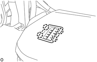
Detach the 4 claws and remove the side defroster nozzle LH.
55969
36.REMOVE NO. 2 DEFROSTER NOZZLE OPENING COVER (w/o Heater)
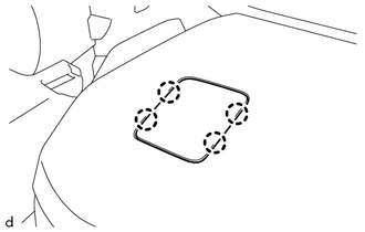
Detach the 4 claws and remove the No. 2 defroster nozzle opening cover.
45130
37.REMOVE HORN BUTTON ASSEMBLY
45100
38.REMOVE STEERING WHEEL ASSEMBLY
45287
39.REMOVE LOWER STEERING COLUMN COVER
45286B
40.REMOVE UPPER STEERING COLUMN COVER
55301
41.REMOVE INSTRUMENT PANEL SUB-ASSEMBLY
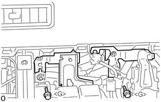
w/o Passenger Side Airbag:
Remove the 2 bolts <G>.
w/ Outer Mirror Switch:
Detach the clamp.
w/ Antenna:
Disconnect the connector and detach the clamp.
Disconnect the connector and detach the 4 clamps.
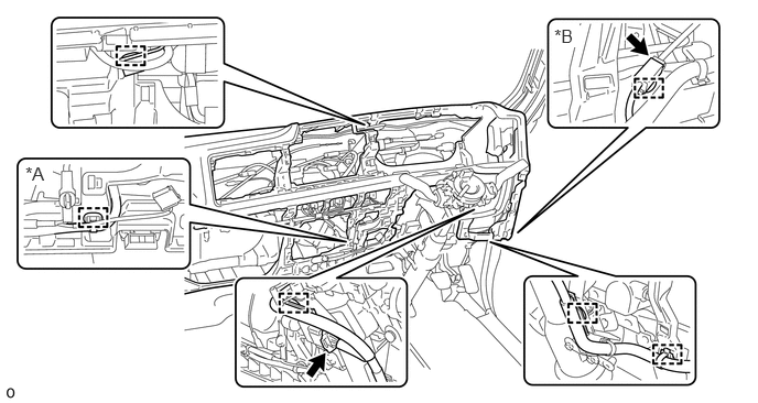
| *A | w/ Outer Mirror Switch | *B | w/ Antenna |
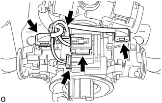
Disconnect the 5 connectors.
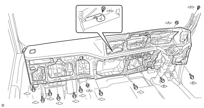
Remove the 2 clips <H>.
Remove the 2 nuts <A>, 2 bolts <B> and 8 bolts <C> and instrument panel sub-assembly.