2GR-FE ENGINE CONTROL VVT SENSOR INSTALLATION
PROCEDURE

 1.INSTALL VVT SENSOR (for Bank 2 Exhaust Side)
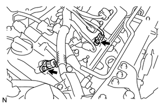
Install the VVT sensor with the bolt.
- Torque:
- 10 N*m (102 kgf*cm, 7 ft.*lbf)
Connect the VVT sensor connector.
2.INSTALL VVT SENSOR (for Bank 2 Intake Side)
Install the VVT sensor with the bolt.
- Torque:
- 10 N*m (102 kgf*cm, 7 ft.*lbf)
Connect the VVT sensor connector.
3.INSTALL VVT SENSOR (for Bank 1 Exhaust Side)
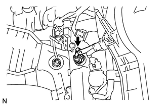
Install the VVT sensor with the bolt.
- Torque:
- 10 N*m (102 kgf*cm, 7 ft.*lbf)
Connect the VVT sensor connector.
4.INSTALL VVT SENSOR (for Bank 1 Intake Side)
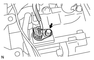
Install the VVT sensor with the bolt.
- Torque:
- 10 N*m (102 kgf*cm, 7 ft.*lbf)
Connect the VVT sensor connector.
17190
5.INSTALL INTAKE AIR SURGE TANK ASSEMBLY
17705
6.INSTALL AIR CLEANER CAP
7.INSTALL COWL TOP OUTER PANEL WITH WINDSHIELD WIPER MOTOR AND LINK
Install the cowl top outer panel with windshield wiper motor and link (See page Vehicle Interior>WIPER / WASHER>FRONT WIPER MOTOR>INSTALLATION).
8.CONNECT CABLE TO NEGATIVE BATTERY TERMINAL
9.INSPECT FOR ENGINE OIL LEAK
10.PERFORM INITIALIZATION
Perform initialization (See page General>INTRODUCTION>REPAIR INSTRUCTION>INITIALIZATION).
- NOTICE:
-
Certain systems need to be initialized after disconnecting the cable from the negative (-) battery terminal.