2AZ-FE ENGINE CONTROL KNOCK SENSOR INSTALLATION
PROCEDURE

 89615
1.INSTALL KNOCK SENSOR
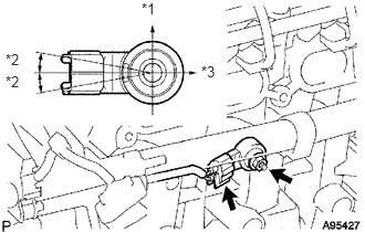
Install the sensor with the nut.
- Torque:
- 20 N*m (204 kgf*cm, 15 ft.*lbf)
- NOTICE:
-
Make sure that the knock sensor is in the correct position.
Text in Illustration *1 Up *2 10° *3 RH
Connect the sensor connector.
17135A
2.INSTALL INTAKE MANIFOLD INSULATOR
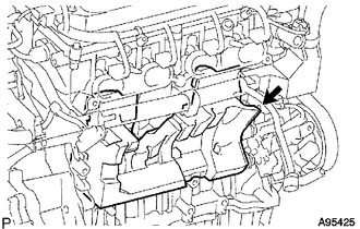
Install the intake manifold insulator onto the cylinder block.
17111
3.INSTALL INTAKE MANIFOLD
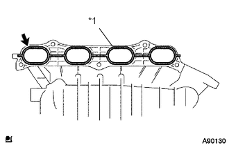
Install a new gasket into the intake manifold.
| *1 | New Gasket |
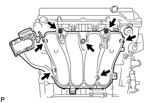
Install the intake manifold with the 5 bolts and 2 nuts.
- Torque:
- 30 N*m (305 kgf*cm, 22 ft.*lbf)
Fit the union to check valve hose into the vacuum hose clamp.
Install the wire harness clamp.
Connect the camshaft timing oil control valve connector.
Connect the union to check valve hose to the brake booster.
11000
4.INSTALL ENGINE ASSEMBLY
Install the engine assembly to the vehicle (See page Engine / Hybrid System>2AZ-FE ENGINE MECHANICAL>ENGINE ASSEMBLY>INSTALLATION).
28800
5.CONNECT CABLE TO NEGATIVE BATTERY TERMINAL
6.ADD ENGINE COOLANT
7.CHECK FOR ENGINE COOLANT LEAKAGE
8.CHECK FOR FUEL LEAKAGE
9.PERFORM INITIALIZATION
Perform initialization (See page General>INTRODUCTION>REPAIR INSTRUCTION>INITIALIZATION).
- NOTICE:
-
Certain systems need to be initialized after disconnecting the cable from the negative (-) battery terminal.