2AZ-FE COOLING RADIATOR INSTALLATION
PROCEDURE

 16711
1.INSTALL FAN SHROUD WITH FAN MOTOR
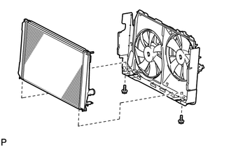
Install the fan shroud with fan motor to the radiator with the 2 bolts.
- Torque:
- 11 N*m (112 kgf*cm, 8 ft.*lbf)
16400
2.INSTALL RADIATOR ASSEMBLY WITH FAN SHROUD AND FAN MOTOR
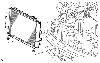
Install the 2 lower radiator support cushions.
Install the radiator with fan shroud and fan motor.
Install the 4 fan shroud cushions to the cooler condenser.
Attach the cooler condenser to the radiator.
16712
3.INSTALL NO. 2 FAN SHROUD
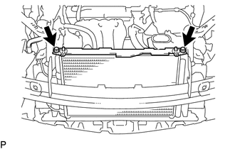
Install the No. 2 fan shroud with the 2 bolts.
- Torque:
- 11 N*m (112 kgf*cm, 8 ft.*lbf)
53205
4.INSTALL RADIATOR UPPER SUPPORT SUB-ASSEMBLY
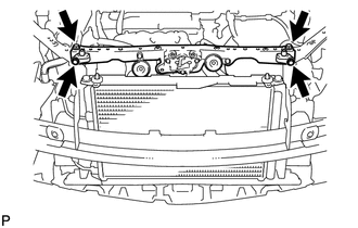
Install the support with wire harness with the 4 bolts.
- Torque:
- 30 N*m (306 kgf*cm, 22 ft.*lbf)
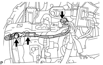
Install the wire ground cable's bolt to the radiator support LH side.
- Torque:
- 8.0 N*m (82 kgf*cm, 71 in.*lbf)
Attach the wire harness's clamp to the radiator support LH side.
17751
5.INSTALL NO. 1 AIR CLEANER INLET
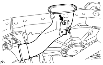
Install the inlet with the clip.
16533
6.INSTALL RADIATOR SUPPORT UPPER BRACKET
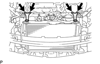
Install the 2 brackets with the 4 bolts.
- Torque:
- 19 N*m (194 kgf*cm, 14 ft.*lbf)
53209B
7.INSTALL HOOD LOCK SUPPORT BRACE SUB-ASSEMBLY
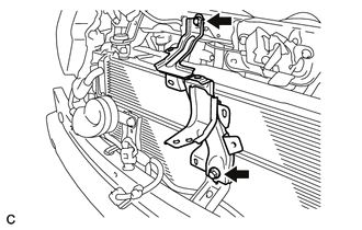
Install the hood lock support brace sub-assembly with the 2 bolts.
- Torque:
- 31 N*m (316 kgf*cm, 23 ft.*lbf)
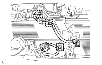
Connect the 3 wire harness clamps to the hood lock support brace sub-assembly.
8.CONNECT COOLING FAN MOTOR CONNECTOR
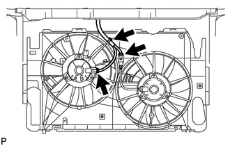
Attach the claw.
Connect the No. 1 and No. 2 fan motor connectors.
16268
9.INSTALL NO. 1 WATER BY-PASS PIPE
Install the pipe with the 2 bolts.
- Torque:
- 19 N*m (194 kgf*cm, 14 ft.*lbf)
Connect the No. 1 water by-pass hose to the reservoir, and attach the clamp to the radiator support.
Connect the No. 3 water by-pass hose to the radiator.
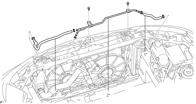
| *1 | No. 1 Water By-Pass Hose | *2 | No. 1 Water By-Pass Pipe |
| *3 | No. 3 Water By-Pass Hose | - | - |
81150
10.INSTALL HEADLIGHT ASSEMBLY
Install the headlight assembly (see page Vehicle Interior>LIGHTING>HEADLIGHT ASSEMBLY(except LED Headlight)>INSTALLATION).
32921
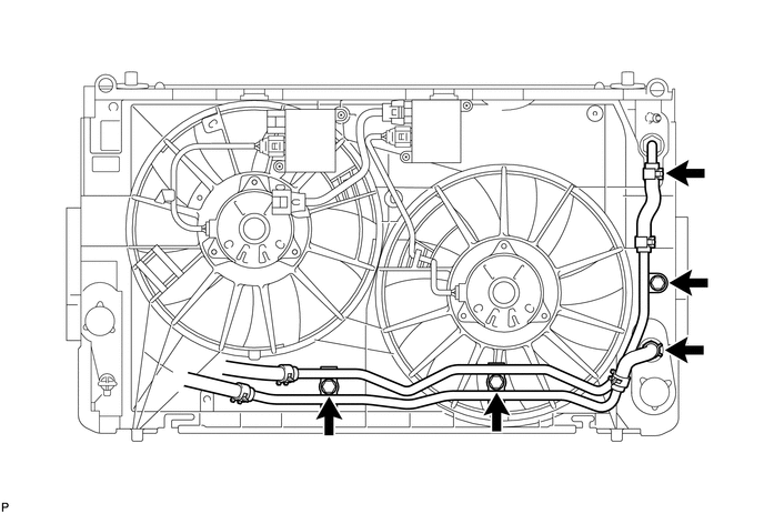
11.CONNECT NO. 1 OIL COOLER INLET TUBE (w/ Oil Cooler)
Connect the oil cooler hose inlet and outlet to the radiator.
Install the tube to the radiator with the 3 bolts.
- Torque:
- 5.5 N*m (56 kgf*cm, 49 in.*lbf)
16572D
12.CONNECT NO. 2 RADIATOR HOSE
16571C
13.CONNECT NO. 1 RADIATOR HOSE
Connect the radiator hose to the radiator, engine and No. 1 water by-pass pipe.
28800
14.INSTALL BATTERY
74404B
15.INSTALL BATTERY CLAMP SUB-ASSEMBLY
Install the battery clamp with the bolt and nut.
- Torque:
- 46 N*m (469 kgf*cm, 34 ft.*lbf)
for bolt
- 5.0 N*m (51 kgf*cm, 44 in.*lbf)
for nut
Connect the cable to the positive (+) battery terminal.
- Torque:
- 5.4 N*m (55 kgf*cm, 48 in.*lbf)
16.CONNECT CABLE TO NEGATIVE BATTERY TERMINAL
- Torque:
- 5.4 N*m (55 kgf*cm, 48 in.*lbf)
17.ADD ENGINE COOLANT
18.INSPECT FOR COOLANT LEAK
51441
19.INSTALL NO. 1 ENGINE UNDER COVER
20.PERFORM INITIALIZATION
Perform initialization (see page General>INTRODUCTION>REPAIR INSTRUCTION>INITIALIZATION).
- NOTICE:
-
Certain systems need to be initialized after disconnecting and reconnecting the cable from the negative (-) battery terminal.