BRAKE BRAKE PEDAL INSTALLATION
PROCEDURE

 47110
1.INSTALL BRAKE PEDAL SUPPORT ASSEMBLY
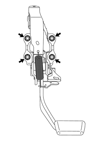
Install the support with the 4 nuts.
- Torque:
- 13 N*m (130 kgf*cm, 9 ft.*lbf)
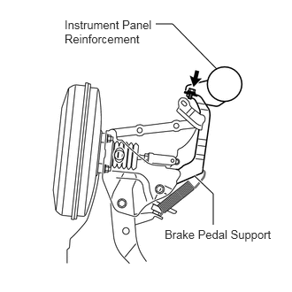
Install the bolt to the support.
- Torque:
- 24 N*m (245 kgf*cm, 18 ft.*lbf)
47264A
2.INSTALL PUSH ROD PIN
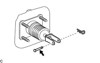
Apply lithium soap base glycol grease to the push rod pin.

|
Lithium soap base glycol grease |
Install the push rod pin to the push rod clevis.
- NOTICE:
-
The push rod pin must be installed as shown in the illustration.
Install a new clip to the push rod pin.
- NOTICE:
-
The clip must be installed as shown in the illustration.
- HINT:
-
Only the clips in the illustration will be supplied.
84340
3.INSTALL STOP LIGHT SWITCH ASSEMBLY
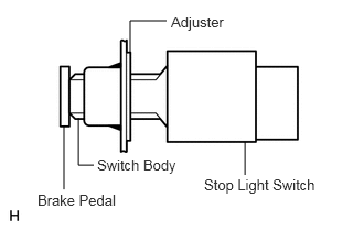
Insert the switch into the adjuster until the switch body touches the pedal.
- NOTICE:
-
Do not depress the pedal.
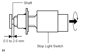
Turn the switch a quarter turn clockwise.
- Torque:
- 0.294 to 1.03 N*m (3.0 to 10.5 kgf*cm, 2.6 to 9.1 in.*lbf)
- NOTICE:
-
Do not depress the pedal.
Check the switch clearance.
- Standard stop light switch clearance:
0.5 to 2.6 mm (0.020 to 0.102 in.)
4.CONNECT CONNECTOR
Connect the brake pedal load sensing switch connector.
Connect the stop light switch connector.
5.INSPECT AND ADJUST BRAKE PEDAL
(See page Brake>BRAKE>BRAKE PEDAL>ADJUSTMENT)
55312
6.INSTALL LOWER INSTRUMENT PANEL
Install the lower instrument panel (see page Vehicle Interior>INTERIOR PANEL>LOWER INSTRUMENT PANEL>INSTALLATION).
55302A
7.INSTALL UPPER INSTRUMENT PANEL
Install the upper instrument panel (see page Vehicle Interior>INTERIOR PANEL>UPPER INSTRUMENT PANEL>INSTALLATION).
8.CONNECT CABLE TO NEGATIVE BATTERY TERMINAL
- NOTICE:
-
When disconnecting the cable, some systems need to be initialized after the cable is reconnected (See page General>INTRODUCTION>REPAIR INSTRUCTION>INITIALIZATION).