BRAKE BRAKE BOOSTER(for 2AZ-FE RHD) INSTALLATION
PROCEDURE

 44696
1.INSTALL CHECK VALVE GROMMET
Install the grommet to the booster.
44730
2.INSTALL BRAKE VACUUM CHECK VALVE ASSEMBLY
Install the check valve to the grommet.
44785
3.INSTALL BRAKE BOOSTER GASKET
Install a new gasket to the booster.
47264D
4.INSTALL BRAKE MASTER CYLINDER PUSH ROD CLEVIS
Install the push rod clevis to the booster.
Temporarily tighten the push rod clevis lock nut.
- HINT:
-
The push rod clevis lock nut will be tightened to a torque specification in the "CHECK AND ADJUST BRAKE PEDAL HEIGHT" procedures.
44610
5.INSTALL BRAKE BOOSTER ASSEMBLY
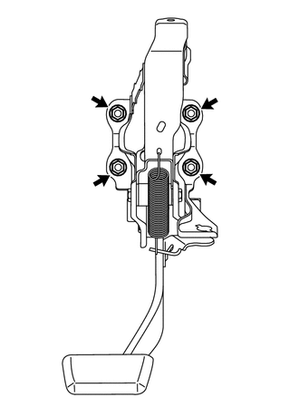
Install the booster with the 4 nuts.
- Torque:
- 13 N*m (130 kgf*cm, 9 ft.*lbf)
47264A
6.INSTALL PUSH ROD PIN
Apply lithium soap base glycol grease to the push rod pin.
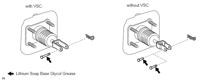
Install the push rod pin to the push rod clevis.
- NOTICE:
-
The push rod pin must be installed as shown in the illustration.
- HINT:
-
Each of push rod pins is interchangeable as shown in the illustration (without VSC).
Install a new clip to the push rod pin.
- NOTICE:
-
The clip must be installed as shown in the illustration.
- HINT:
-
Only the clips in the illustration will be supplied.
7.CONNECT VACUUM HOSE
Connect the vacuum hose to the check valve.
47201
8.INSTALL BRAKE MASTER CYLINDER SUB-ASSEMBLY
9.BLEED BRAKE SYSTEM
(See page Brake>BRAKE>BRAKE FLUID>BLEEDING)
10.INSPECT AND ADJUST BRAKE PEDAL
(See page Brake>BRAKE>BRAKE PEDAL>ADJUSTMENT)